
Installation Instructions Manual

16 Kinetix 6000M Integrated Drive-Motor
Rockwell Automation Publication MDF-IN001B-EN-P - August 2013
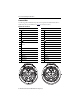
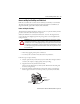
Node Address Switches
A unique network address for each IDM unit is set on the S1 and S10 rotary address switches.
Valid IDM addresses are 01…99. The least significant digit (0…9) is set on switch S1, and switch
S10 sets the most significant digit (10…90). Apply 0.6 N•m (5 lb•in) of torque to the switch
cover to environmentally seal the opening.
Refer to IDM Unit Connectors and Indicators on page 6
for connector location.
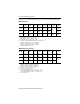
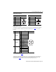
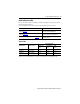
Network and Drive Status Indicators
Two multi-color indicators provide IDM network (N) and drive (D) status. Refer to IDM Unit
Connectors and Indicators on page 6 for status indicator locations.
Status Display Network (N) Drive (D)
Off No communication No power
Alternating green/red – Self test
Flashing green
(1)
(1) Flashing rate is once per second. The fast flashing rate is twice per second, and the slow flashing rate is once every two seconds. A flash is defined as
one complete on/off cycle.
Establishing communication Standby
(2)
(2) Drive status is Standby while waiting for the network communication to be established and transition to a Normal operation state.
Fast flashing green
(1)
Firmware update in process –
Slow flashing green
(1)
Firmware update in process
(on a different IDM unit)
–
Green Communication ready Normal operation
Flashing red
(1)
–Recoverablefault
(3)
(3) A reset or cycling the power can clear a recoverable fault (depending on the state of the IDM unit).
Red Duplicate address Non-recoverable fault
(4)
(4) A non-recoverable fault requires power cycling to clear the fault and/or a hardware configuration modification performed while power is removed.