
Installation Instructions Manual

Kinetix 6000M Integrated Drive-Motor 15
Rockwell Automation Publication MDF-IN001B-EN-P - August 2013
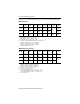
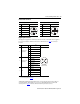
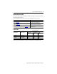
Network Connector Pinout
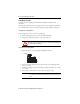
Digital Input Connectors
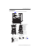
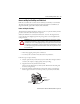
24V digital I/O signals from machine-based sensors interface to the IDM unit through three
I/O connectors. Refer to IDM Unit Connectors and Indicators on page 6 for connector
locations.
Allen-Bradley® Bulletin 889D and 879D micro-style patchcords, splitters, and V-cables are
compatible with the M12 digital I/O connectors on the IDM unit. Refer to Cables and
Accessory Kits on page 19
for a list of Kinetix 6000M system cable resources.
Network Output Connector Network Input Connector
Pin Signal Name Female Connector Pin Signal Name Male Connector
1 TX+ 1 RX+
2 RTN RX+ 2 RTN TX-
3 RTN RX- 3 RTN TX+
4 TX- 4 RX-
5 REF 5 REF
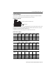
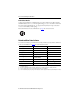
ID Digital Inputs Pin Signal Name
(1)
(1) Detailed information about the digital inputs is available in the Kinetix 6000M Integrated Drive-Motor
System User Manual, publication
2094-UM003
.
Connector Pinout
1
Overtravel - and
Registration 2
1 I/O 24V +
2Overtravel -
3 I/O 24V COM
4 Registration 2
5 Shield/Chassis Ground
2
Overtravel + and
Registration 1
1 I/O 24V +
2Overtravel +
3 I/O 24V COM
4 Registration 1
5 Shield/Chassis Ground
3 Home
1 I/O 24V +
2 Reserved
3 I/O 24V COM
4Home
5 Shield/Chassis Ground
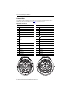
1
4
2
35
1
2
3
4
5
1
4
2
35
Female Connector