
Installation Instructions Manual

14 Kinetix 6000M Integrated Drive-Motor
Rockwell Automation Publication MDF-IN001B-EN-P - August 2013
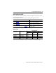
Connector Data
The following tables and illustrations provide connector pinouts for the IDM units. Refer to
IDM Unit Connectors and Indicators on page 6 for connector locations.
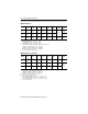
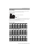
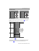
Hybrid Connector Pinout
Hybrid Output Connector Hybrid Input Connector
Pin Signal Name Pin Signal Name
A DC + A DC +
B DC - B DC -
C 42V + C 42V +
D 42V COM D 42V COM
E Protective Earth (PE) Ground E Protective Earth (PE) Ground
1
Reserved
1 Reserved
2 2 Brake 24V +
3 3 Brake 24V COM
4 Safety Enable 1+ 4 Safety Enable 1+
5 Safety Enable - 5 Safety Enable -
6 Safety Enable 2+ 6 Safety Enable 2+
7 IDM CAN HI 7 IDM CAN HI
8 IDM CAN LO 8 IDM CAN LO
9 IDM SYSOKOUT 9 IDM SYSOKIN
10 IDM SYSOKRTN 10 IDM SYSOKRTN
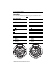
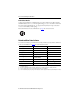
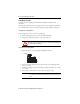
D
5
42
63
1
CB
A
E
9
7
8
10
Female Connector
A
1
24
36
5
BC
D
E
7
8
9
10
Male Connector