Installation Instructions Kinetix 6000M Integrated Drive-Motor Catalog Numbers MDF-SB1003, MDF-SB1153, MDF-SB1304 Topic Page Important User Information 2 About the Kinetix 6000M Integrated Drive-Motor 3 Catalog Number Explanation 4 Kinetix 6000M Integrated Drive-Motor System Cable Diagram 5 IDM Unit Connectors and Indicators 6 Before You Begin 7 Installing the Integrated Drive-Motor 8 Product Dimensions 11 Load Force Ratings 13 Connector Data 14 Network and Drive Status Indicators 16
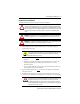
Kinetix 6000M Integrated Drive-Motor Important User Information Read this document and the documents listed in the additional resources section about installation, configuration, and operation of this equipment before you install, configure, operate, or maintain this product. Users are required to familiarize themselves with installation and wiring instructions in addition to requirements of all applicable codes, laws, and standards.
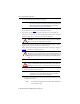
Kinetix 6000M Integrated Drive-Motor 3 About the Kinetix 6000M Integrated Drive-Motor Kinetix® 6000M integrated drive-motor (IDM) systems include up to 16 integrated drive-motor (IDM) units, along with an IDM power interface module (IPIM). IDM units are mounted directly on the machine and the IPIM module mounts on the Bulletin 2094 power rail. IDM units and the IPIM module are compatible with only 400V-class Kinetix 6000 or Kinetix 6200 multi-axis drive systems.
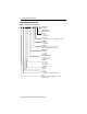
Kinetix 6000M Integrated Drive-Motor Catalog Number Explanation MD F - S B xxx x x - Q x 8 x B - S Safety Option S = Safe off Mounting Flange B= IEC metric oversize Brake 2 = No brake 4 = 24V DC brake Connectors 8 = Circular (SpeedTec) connector, right angle, 180° rotatable Shaft Key J = Shaft key K = No shaft key Feedback Q = 524,288 counts per revolution, 4096 turns high-resolution multi-turn absolute encoder Rated Speed F = 3000 rpm H = 3500 rpm P = 5000 rpm Magnet Stack Length 3 = 76.2 mm (3.0 in.
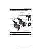
Kinetix 6000M Integrated Drive-Motor 5 Kinetix 6000M Integrated Drive-Motor System Cable Diagram 2090-CHBIFS8-12AAxx IPIM-to-IDM Hybrid Cable Connects the IPIM Module to the First IDM Unit 2094-SEPM-B24-S IPIM Module 2090-CHBP8S8-12AAxx Hybrid Cable 2090-CTHP8 Hybrid Terminator R R G G 2090-CNSSPSS-12AAxx or 2090-CNSSPRS-AAxx (shown) Network Cable R R G G 2090-CTSRP Network Terminator MDF-SB1xxx First IDM Unit MDF-SB1xxx Last IDM Unit 2090-CNSSPSS-AAxx, 2090-CNSRPRS-AAxx (shown), 2090-CNSSPRS-AAxx
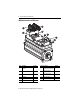
Kinetix 6000M Integrated Drive-Motor IDM Unit Connectors and Indicators 2 3 1 4 10 11 9 8 5 7 6 Item Description Panel ID Item Description Panel ID 1 Network In – 7 Digital Input/Output 1: Registration 2 and Overtravel - 1 2 Hybrid In – 8 Digital Input/Output 2: Registration 1 and Overtravel + 2 3 Hybrid Out – 9 Digital Input/Output 3: Home and not used 3 4 Network Out – 10 Drive status indicator D 5 Node Address LSB (0…9) S1 11 Network status indicator N 6 Nod
Kinetix 6000M Integrated Drive-Motor 7 Before You Begin Remove all packing material, wedges, and braces from within and around the components. After unpacking, check the item nameplate catalog number against the purchase order. ATTENTION: Do not attempt to open or modify the IDM unit. This manual describes modifications that you can perform in the field, but do not attempt other changes. Only qualified Allen-Bradley technicians can service an IDM unit.
Kinetix 6000M Integrated Drive-Motor Installing the Integrated Drive-Motor Installing the IDM unit involves the proper alignment on the machine, effective cable shield grounding, mounting the IDM unit, and connecting the cables. Aligning the IDM Unit The IDM unit can be mounted in any position. The mounting pilot aides in aligning the IDM unit on a machine. Refer to Product Dimensions on page 11 for these dimensions. Stainless steel mounting fasteners are preferred.
Kinetix 6000M Integrated Drive-Motor 9 Mount and Connect the IDM Unit To install an IDM unit, follow these procedures and recommendations. ATTENTION: The IDM unit connects to an IDM power interface module (IPIM) that stores residual voltage for an extended period of time. Do not connect an IDM to an IPIM module immediately after removing power to the IPIM module. Allow the residual power stored in the IPIM module to dissipate for 60 seconds after power is removed from the IDM system.
Kinetix 6000M Integrated Drive-Motor 4. Position the IDM unit on the machine in any position. IMPORTANT IDM units with a brake (MDF-SBxxxxP-QJ84B-S) can require the use of a manual brake-release cable to release the brake prior to rotating the shaft so the IDM unit aligns with the machine mounts. Refer to the Manual Brake Release Cable Installation Instructions, publication 2090-IN037, for more information. 5. Mount and align the IDM unit by using stainless steel bolts.
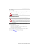
Kinetix 6000M Integrated Drive-Motor 11 Product Dimensions Refer to the tables on page 12 for the physical dimensions shown in this figure. L L- LB LB LD LE Connector housing can be rotated one-time within a range of 180°. D See Detail A LA MDF-SB1003P-Qx82B-S motor shown 63.6 (2.50) 2.74 (0.108) Use shaft end mark or shaft key to orient encoder absolute position (0° ±10°). 42.3 (1.66) Shaft End Threaded Hole MDF-SB1003 IDM Units Thread - M5 x 0.8-6H Thread Depth - 12.5 (0.
Kinetix 6000M Integrated Drive-Motor Dimensions are for non-brake IDM units; footnotes provide tolerances and brake dimensions. IDM Unit Dimensions MDF-SB AD mm (in.) D (1) mm (in.) F mm (in.) G mm (in.) HD mm (in.) L (2) mm (in.) 1003 173.8 (6.84) 16.0 (0.629) 5.0 (0.197) 12.95 (0.510) 221.0 (8.70) 271.3 (10.685) 1153 178.2 (7.01) 19.0 (0.740) 6.0 (0.236) 15.40 (0.606) 229.0 (9.02) 271.2 (10.675) 1304 185.8 (7.31) 24.0 (0.945) 8.0 (0.315) 19.82 (0.780) 244.7 (9.63) 310.6 (12.
Kinetix 6000M Integrated Drive-Motor 13 Load Force Ratings An IDM unit can operate with a sustained shaft load. The figure shows radial and axial load force locations, and the tables provide maximum values for each force. Load Forces on the Shaft Radial Load Force is applied at center of shaft extension. Axial Load Force The tables represent 20,000 hour L10 bearing fatigue life at various loads and speeds.
Kinetix 6000M Integrated Drive-Motor Connector Data The following tables and illustrations provide connector pinouts for the IDM units. Refer to IDM Unit Connectors and Indicators on page 6 for connector locations.
Kinetix 6000M Integrated Drive-Motor 15 Network Connector Pinout Network Output Connector Pin Signal Name 1 TX+ 2 RTN RX+ Network Input Connector Female Connector 4 Pin Signal Name 1 RX+ 2 RTN TX- Male Connector 4 1 3 RTN RX- 4 TX- 5 REF 3 5 1 2 3 RTN TX+ 4 RX- 5 REF 3 5 2 Digital Input Connectors 24V digital I/O signals from machine-based sensors interface to the IDM unit through three I/O connectors.
Kinetix 6000M Integrated Drive-Motor Node Address Switches A unique network address for each IDM unit is set on the S1 and S10 rotary address switches. Valid IDM addresses are 01…99. The least significant digit (0…9) is set on switch S1, and switch S10 sets the most significant digit (10…90). Apply 0.6 N•m (5 lb•in) of torque to the switch cover to environmentally seal the opening. Refer to IDM Unit Connectors and Indicators on page 6 for connector location.
Kinetix 6000M Integrated Drive-Motor 17 Remove and Replace Shaft Keys and Shaft Seals IDM units are available with or without a slot for a shaft key, but a shaft key is recommended. The shaft seal provides environmental sealing for the integrated drive-motor. IDM units are shipped with a PTFE (polytetrafluoroethylene) shaft seal installed.
Kinetix 6000M Integrated Drive-Motor Remove and Replace Shaft Seals Shaft seals must be lubricated by using a food-grade polyurea base grease, such as ChevronSM FM (NLGI 2). Shaft seals are typically replaced at 12-month intervals. Lubricant is supplied the kit. ATTENTION: Damage to the shaft surface where the seal makes contact can cause excessive wear and early failure of the shaft seal. Use care to prevent scratching or damage to the mounting surface or to the IDM shaft.
Kinetix 6000M Integrated Drive-Motor 19 Cables and Accessory Kits Factory manufactured cables are available in standard cable lengths. They provide the required shielding and signal termination. For more cable information, contact your nearest Rockwell Automation sales office. Resource Description Kinetix Motion Accessories Specifications Technical Data, publication GMC-TD004 Provides cable catalog numbers and descriptions specifically for Kinetix 6000M IDM systems.
Kinetix 6000M Integrated Drive-Motor Sealing Air Accessory Kit The sealing air pressure kit (catalog number MPS-AIR-PURGE) is available for field installation. The kit provides a quick-release female air fitting. Positive air pressure applied to the IDM unit creates an additional level of protection against the ingress of foreign substances and moisture. Sealing Air Accessory Kit Guidelines You must supply these items, to connect to the sealing plug: • Plastic air tubing must be 4 mm (5/32 in.
Kinetix 6000M Integrated Drive-Motor 21 Specifications Attribute Mounting clearance Value (1) Temperature, operating 100 mm (3.9 in.
Kinetix 6000M Integrated Drive-Motor Motor Overload Protection This servo drive uses solid-state motor overload protection that operates in accordance with UL 508C. Motor overload protection is provided by algorithms (thermal memory) that predict actual motor temperature based on operating conditions as long as control power is continuously applied. However, when control power is removed, thermal memory is not retained.
Kinetix 6000M Integrated Drive-Motor 23 Additional Resources These documents contain additional information concerning related products from Rockwell Automation.
Rockwell Automation Support Rockwell Automation provides technical information on the Web to assist you in using its products. At http://www.rockwellautomation.com/support you can find technical and application notes, sample code, and links to software service packs. You can also visit our Support Center at https://rockwellautomation.custhelp.com/ for software updates, support chats and forums, technical information, FAQs, and to sign up for product notification updates.