
User guide


Rockwell Automation Publication 2094-UM003A-EN-P - May 2012 49
Kinetix 6000M System Connector Data Chapter 4
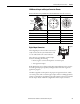
Table 14 - Understanding the Digital Inputs
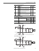
Table 15 - Digital Input Specifications
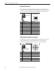
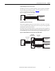
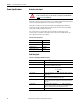
Figure 18 - Standard Digital Input Circuits
(1) 24V DC source (range) = 21.6V - 26.4V (supplied by IPIM, not to exceed 250 mA total). Maximum current input = 10 mA.
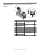
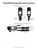
Figure 19 - High Speed Digital Input Circuits
Pin Connector Signal Description
Capture
Time
Edge/Level
Sensitive
4 1 HOME Optically isolated, single-ended active high signal. Current
loading is nominally 10 mA. Home switch (normally open
contact) inputs for each axis require 24V DC (nominal).
30 ms Level
42/3 REG1
REG2
Fast registration inputs are required to inform the motor
interface to capture the positional information with less
than 4 μs uncertainty. Optically isolated, single-ended
active high signal. Current loading is nominally 10 mA. A 24V
DC input is applied to this terminal.
500 ns Edge
22/3 OT+
OT-
Overtravel detection is available as an optically isolated,
single-ended active high signal. Current loading is nominally
10 mA per input. The pos/neg limit switch (normally closed
contact) inputs for each axis require 24V DC (nominal).
30 ms Level
Parameter Description Min Max
On-state voltage Voltage applied to the input, with
respect to IOCOM, to assure an on-state.
HOME, and OT+/OT- 21.6V 26.4V
REG1 and REG2 21.6V 26.4V
On-state current Current flow to guarantee an on-state. 3.0 mA 10.0 mA
Off-state voltage Voltage applied to the input, with respect to IOCOM, to assure an
off-state.
-1.0V 3.0V
3k Ω
0.1 μF
511 Ω
INPUT
IO_COM
I/O SUPPLY
Customer-supplied
Input Device
24V DC
(1)
IDM
2.49k Ω
1.27k Ω
INPUT
IO_COM
I/O SUPPLY
0.001 μF
IDM
Customer-supplied
Device
24V DC