
User guide


42 Rockwell Automation Publication 2094-UM003A-EN-P - May 2012
Chapter 4 Kinetix 6000M System Connector Data
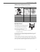
EtherNet/IP Connectors
Two connectors are provided for firmware upgrades, troubleshooting, and
integration with Logix. The Ethernet ports also support a web browser interface
to provide access to status information for the IPIM module and IDM units.
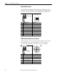
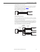
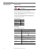
IPIM Module Network Connector Pinouts
The IDM system network is routed by using 2090-CNSxPxS-AAxx cables. A
2090-CNSSPRS-AAxx or 2090-CNSSPSS-AAxx cable is required for
connection to the IPIM module. The connector type is B-coded M12.
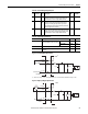
Pin Signal Description Signal Name
1 Transmit+ TD+
2 Transmit- TD-
3Receive+ RD+
4Reserved –
5Reserved –
6Receive- RD-
7Reserved –
8Reserved –
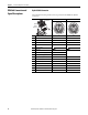
Pin Signal Description Signal Name
1 Transmit (TX+) to IDM unit TX+
2 Return (RX-) from IDM unit RTN RX-
3 Return (RX+) from IDM unit RTN RX+
4 Transmit (TX-) to IDM unit TX-
5 Reference signal REF
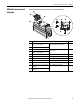
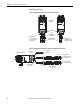
EtherNet/IP Ports
1
8
8-pin Control Module
Ethernet Connector
IDM Network
Connector
1
2
3
4
5