
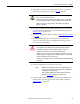
User guide


38 Rockwell Automation Publication 2094-UM003A-EN-P - May 2012
Chapter 4 Kinetix 6000M System Connector Data
IPIM Module Connectors and
Indicators
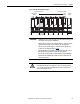
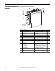
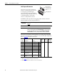
Figure 11 - Module Connectors and Indicators
Item Description See page
➊ Hybrid cable DC bus connector Termination point for +/- DC and PE 39
➋ Hybrid cable communication signals
connector
Connection point for IDM unit power and
communication
39
➌ Safe-off connector Termination point for safety signals 40
➍ Enable connector Enable input to the IDM system 41
➎ Sercos fiber-optic connectors Transmit and receive fiber-optic connectors 41
➏ LCD display Allows ethernet configuration and system status 66
➐ Navigation buttons Four buttons provide access and navigation
when using the LCD display
66
➑ Status indicators
DC Bus
Control Bus
Port 1 and Port 2
Module Status
Network Status
DC bus status
Control bus status (present, faulted)
Communication status of the EtherNet/IP ports
IPIM module status (operating, standby, faulted)
Indicates IDM system network status
90
➒ EtherNet/IP ports Two Ethernet ports are provided 42
➓ IDM network cable connector Connection point for network cable to first IDM
unit
42
SH1
42+
42-
SH2
CN-
CN+
OUT
RTN
SH3
SE1
SE-
SE2
ETHERNET 1
ETHERNET 2
NETWORK
➋
➊
➌
➏
➍
➎
➒
➑
➐
➓