
User guide

Rockwell Automation Publication 2094-UM003A-EN-P - May 2012 31
Mounting the Kinetix 6000M System Chapter 3
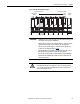
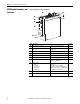
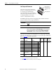
Figure 10 - Module Mounting Order Example
IMPORTANT
The IAM must be positioned in the leftmost slot of the power rail. Position your
other modules to the right of the IAM module.
Mount modules according to power utilization (highest to lowest) from left to
right starting with the highest power utilization. If power utilization is
unknown, position modules (highest to lowest) from left to right based on
continuous power rating (kW). Refer to page 30
.
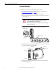
The shunt module must be installed to the right of the last module. Only slot-
filler modules may be installed to the right of the shunt module.
Do not mount the shunt module on power rails with a follower IAM module.
Common bus follower IAM modules disable the internal, rail mounted, and
external shunt modules.
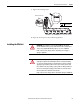
SHOCK HAZARD: To avoid personal injury due to electrical shock, place a
2094-PRF slot-filler module in all empty slots on the power rail. Any power rail
connector without a module installed will disable the drive system; however,
control power will still be present.
Highest Power Utilization Lowest Power Utilization
Integrated Axis
Module
Shunt
Module
Slot Filler
Module
IPIM Module Axis Modules