
User guide

Rockwell Automation Publication 2094-UM003A-EN-P - May 2012 25
Planning the Kinetix 6000M System Installation Chapter 2
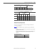
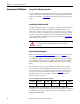
Table 7 - Power Dissipation Specifications - Percent of DC Bus Current
Table 8 - Power Dissipation Specifications - Percent of IPIM Module Control Power
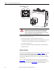
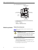
Minimum Clearance Requirements
This section provides information to assist you in sizing your cabinet and
positioning your IDM unit.
Figure 7
illustrates minimum clearance requirements for proper airflow and
installation:
• Additional clearance is required for the cables and wires connected to the
top and front of the module.
• Additional clearance left and right of the power rail is required when the
module is mounted adjacent to noise sensitive equipment or clean
wireways.
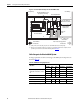
Table 9 - Minimum Cabinet Depth
Power Dissipation as % of DC Bus Current Output Rating
Watts
Heat Dissipation Formula
(1)
(1) x is percent of DC bus current output rating: any value between 0.0 and 1.0.
20% 40% 60% 80% 100%
2 7 142538Y = 33.95x
2
+ 3.18x
Control Power Input
Power Dissipation as % of IPIM Module Control
Power Output Rating
Watts
Heat Dissipation Formulas
(1)
(1) x is percent of IPIM module control power output rating: any value between 0.0 and 1.0.
Frequency
Hz
Voltage
AC 20% 40% 60% 80% 100%
50
120V 22 29 38 48 61 Y = 23.76x
2
+ 20.73x + 16.54
240V 34 42 52 63 76 Y = 18.56x
2
+ 30.19x + 27.41
60
120V 23 27 32 39 46 Y = 14.57x
2
+ 11.40x + 20.01
240V 38 49 62 76 92 Y = 19.63x
2
+ 43.22x + 28.75
Cat. No. Cabinet Depth, Min
2094-SEPM-B24-S 272 mm (10.7 in.)