
User guide

Rockwell Automation Publication 2094-UM003A-EN-P - May 2012 21
Chapter 2
Planning the Kinetix 6000M System Installation
This chapter describes system installation guidelines used in preparation for
mounting your Kinetix 6000M components.
Cable Length Restrictions
and System Sizing
This section provides guidelines for sizing an IDM system. For accurate, detailed
sizing, use Motion Analyzer software version 6.000 or later. For additional
information and a sizing estimation method, refer to Kinetix 6000M System
Sizing on page 127.
When sizing your system, please note the following:
• Motion Analyzer software (version 6.000 or later), should be used for
sizing your system.
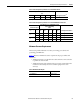
• Maximum cable length between IDM units is 25 m (82 ft).
• Combined cable length for all IDM units connected to a single IPIM
module is 100 m (328 ft).
• Combined motor power and hybrid cable length for all axes on the same
power rail must not exceed 240 m (787 ft).
• The number of IDM units also depends on the use of the safe-off function.
Refer to Using the Safe Torque-off Feature with the Kinetix 6000M
System on page 103 for details.
Topic Page
Cable Length Restrictions and System Sizing 21
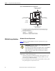
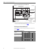
IPIM Module Design Guidelines 22
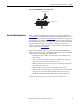
IDM Unit Design Guidelines 26
Electrical Noise Reduction 27
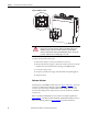
ATTENTION: Plan the installation of your system so that you can perform all
cutting, drilling, tapping, and welding with the system removed from the
enclosure. Because the system is of the open type construction, be careful to
keep any metal debris from falling into it. Metal debris or other foreign matter
can become lodged in the circuitry, which can result in damage to components.