
User guide

128 Rockwell Automation Publication 2094-UM003A-EN-P - May 2012
Appendix D Kinetix 6000M System Sizing
Manually Sizing the
Kinetix 6000M System
Step 1: Calculate the IDM unit control power load current for each
IDM unit.
There are three components to the control power load current for each IDM
unit:
• Constant power load
• Digital input loads
• Brake loads
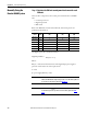
Refer to the IDM unit constant load, brake load, and control power load
specifications shown below.
The digital input load is calculated as follows:
Digital Input Watts =
Where:
Σ I
inputs
= The sum of all load currents on the digital input power supply to
power the sensor and/or the sensor input current
V = 24V
η = power supply efficiency = 80%
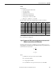
IDM Unit
Cat. No.
with
Brake
Constant Control Power Load
(W)
Brake Control Power Load
(W)
Output Power Rating
(kW)
MDF-SB1003 No 8 0 1.10
MDF-SB1003 Yes 8 15 1.02
MDF-SB1153 No 8 0 1.15
MDF-SB1153 Yes 8 19.5 1.00
MDF-SB1304 No 8 0 1.39
MDF-SB1304 Yes 8 19.5 1.24
IMPORTANT
Confirm that the total IDM unit control power load is less than the specified
limit for the IPIM module output rating (270 W). See the Kinetix Rotary Motion
Specifications Technical Data, publication GMC-TD001
.
IMPORTANT
Confirm that the Σ I
inputs
value is less than the specified limit (200 mA). See
the Kinetix Rotary Motion Specifications Technical Data, publication GMC-
TD001.
Σ I
inputs
*
V
*
η