
User guide


110 Rockwell Automation Publication 2094-UM003A-EN-P - May 2012
Appendix A Using the Safe Torque-off Feature with the Kinetix 6000M System
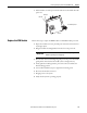
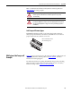
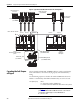
Figure 42 - Typical Kinetix 6000M and Kinetix 6000 Safe-off Configuration
Cascading the Safe Torque-
off Signal
The total number of IAM, AM, and IPIM modules in a single cascaded safety
circuit is limited due to the current carrying capacity of the cascaded safety
wiring.
Use the following equation to calculate the number of IDM units that can be
added to a cascaded safety chain if Kinetix 6000-S safety accessories are used.
Safe-off Control Circuit
Connections
Middle-drive Headers
(2090-XNSM-M)
System 1
Kinetix 6000 and Kinetix 6000M
Systems
Last-drive Header
(2090-XNSM-T)
First-drive Wiring Header
(2090-XNSM-W)
Drive-to-Drive Safe-off Cables
System 2
Kinetix 6000
Drive System
IDM Unit
IDM Unit
1202-C02 1202-C03 1202-C031202-C10
IDM to IDM Hybrid Cable
(2090-CHBP8S8-12AAxx)
Network Cable
(2090-CNSxPxS)
IPIM to IDM Hybrid Cable
(2090-CHBIFS8-12AAxx)
1202-C02
EXAMPLE
Using Figure 42, n equals 5 since there are 5 Kinetix 6000-S modules in the
system. The maximum number of IDM units that can be connected to the
cascaded safety circuit through one or more IPIM modules is:
m = (16-5) x 3 = 33.
m = (16-n) x 3 where:
m = maximum number of IDM units
n = number of Kinetix 6000-S modules in the safety chain.