User Manual Kinetix 6000M Integrated Drive-Motor System Catalog Numbers 2094-SEPM-B24-S, MDF-SB1003P, MDF-SB1153H, MDF-SB1304F
Important User Information Solid-state equipment has operational characteristics differing from those of electromechanical equipment. Safety Guidelines for the Application, Installation and Maintenance of Solid State Controls (publication SGI-1.1 available from your local Rockwell Automation® sales office or online at http://www.rockwellautomation.com/literature/) describes some important differences between solid-state equipment and hard-wired electromechanical devices.
Table of Contents Preface About This Publication . . . . . . . . . . . . . . . . . . . . . . . . . . . . . . . . . . . . . . . . . . . . 7 Conventions Used in This Manual . . . . . . . . . . . . . . . . . . . . . . . . . . . . . . . . . 7 Additional Resources . . . . . . . . . . . . . . . . . . . . . . . . . . . . . . . . . . . . . . . . . . . . . . 7 Chapter 1 Start About the Kinetix 6000M System . . . . . . . . . . . . . . . . . . . . . . . . . . . . . . . . . . 9 Typical Hardware Configurations . . .
Table of Contents Chapter 4 Kinetix 6000M System Connector Data IPIM Module Connectors and Indicators . . . . . . . . . . . . . . . . . . . . . . . . . . IPIM Module Connector and Signal Descriptions . . . . . . . . . . . . . . . . . . Hybrid Cable DC Bus Connector . . . . . . . . . . . . . . . . . . . . . . . . . . . . . Hybrid Cable Communication Signals Connector . . . . . . . . . . . . . . Safe Torque-off Connector. . . . . . . . . . . . . . . . . . . . . . . . . . . . . . . . . . . .
Table of Contents Chapter 6 Configuring the Kinetix 6000M System Configure the Kinetix 6000M Integrated Drive-motor System . . . . . . . Understanding the IPIM Module Display . . . . . . . . . . . . . . . . . . . . . . . . . . Startup Sequence . . . . . . . . . . . . . . . . . . . . . . . . . . . . . . . . . . . . . . . . . . . . . Information Display . . . . . . . . . . . . . . . . . . . . . . . . . . . . . . . . . . . . . . . . . . Tools Menu. . . . . . . . . . . . . . . . . . . . . . . . . . . . . . .
Table of Contents Appendix A Using the Safe Torque-off Feature with the Kinetix 6000M System Certification . . . . . . . . . . . . . . . . . . . . . . . . . . . . . . . . . . . . . . . . . . . . . . . . . . . . Important Safety Considerations . . . . . . . . . . . . . . . . . . . . . . . . . . . . . Category 3 Requirements According to EN ISO 13849-1 . . . . . . . Stop Category Definition . . . . . . . . . . . . . . . . . . . . . . . . . . . . . . . . . . . .
Preface About This Publication This manual provides detailed installation instructions for mounting, wiring, and troubleshooting the Kinetix® 6000M Integrated Drive-Motor (IDM) system including the IDM Power Interface Module (IPIM). For information on wiring and troubleshooting the safe-off feature on your integrated drive-motor system, refer to Appendix A.
Preface Resource Description Kinetix 6000M IPIM Hybrid Terminator Installation Instructions, publication 2090-IN035 Provides detailed terminator information. Kinetix 6000M Network Terminator Installation Instructions, publication 2090-IN036 Kinetix 6000M Hybrid Power Coupler Installation Instructions, publication 2090-IN038 Provides installation information for the Hybrid Power Coupler.
Chapter 1 Start Use this chapter to become familiar with the design and installation requirements for the Kinetix 6000M integrated drive-motor system.
Chapter 1 Start System Component Cat. No. Description Power Rail 2094-PRSx The Bulletin 2094 power rail consists of copper bus bars and a circuit board with connectors for each module. The power rail provides power and control signals from the converter section to adjacent inverters. The IPIM, IAM and AM power modules, shunt module, slot-filler modules mount to the power rail.
Start Typical Hardware Configurations Chapter 1 SHOCK HAZARD: To avoid personal injury due to electrical shock, place a 2094-PRF slot-filler module in all empty slots on the power rail. Any power rail connector without a module installed will disable the 3-phase power; however, control power is still present.
Chapter 1 Start Figure 2 - Typical 2094 Power Rail with Kinetix 6000M System (with LIM) 2090-XXLF-xxxx AC Line Filter (required for CE) 2094-SEPM-B24-S IPIM Module 3-Phase Input Power 2094-PRF Slot-filler Module (required for unused slots) Control Power 2094 Drive System (Kinetix 6000 shown) 2094-BLxxS Line Interface Module (optional component) MAIN VAC Bulletin 2090 Hybrid Cables 2094-PRSx Power Rail 2090-K6CK-Dxxxx Low Profile Connector Kits for I/O, Motor Feedback, and Aux Feedback Bulletin 20
Start Chapter 1 Figure 3 - Typical 2094 Power Rail with Kinetix 6000M System (without LIM) 3-Phase Input Power Line Disconnect Device 2090-XXLF-xxxx Line Filter (required for CE) Input Fusing Control Power Magnetic Contactor 2094-SEPM-B24-S IPIM Module 2094-BSP2 Shunt Module (optional component) 2090-XXLF-xxxx AC Line Filter (required for CE) 2094-PRF Slot-filler Module (required for unused slots) 2094 Drive System (Kinetix 6000 shown) Bulletin 2090 Hybrid Cables 2094-PRSx Power Rail 2090-K6CK-Dxx
Chapter 1 Start In the following example, the leader IAM module is connected to the follower IAM module via the DC common-bus. When planning your panel layout, you must calculate the total bus capacitance of your DC common-bus system to be sure that the leader IAM module is sized sufficiently to pre-charge the entire system.
Start Chapter 1 Figure 4 - Typical Kinetix 6000 with Kinetix 6000M System Common Bus 2090-XXLF-xxxx AC Line Filter (required for CE) Control Power 3-phase Input Power 2094-BSP2 Shunt Module (optional component) 2094-SEPM-B24-S IPIM Module 2094-BCxx-Mxx-S IAM Module Common Bus Leader MAIN VAC 2094-PRF Slot-filler Module (required to fill unused slots) 2094-PRSx Power Rail 2094-BLxxS Line Interface Module (optional component) DC Common Bus 2094-BCxx-Mxx-S IAM Module Common Bus Follower Bulletin 2
Chapter 1 Start The Kinetix 6000M IPIM module uses the EtherNet/IP network to report diagnostics to the controller and for firmware upgrades via ControlFLASH™ software. For more information on Ethernet cables, refer to the Industrial Ethernet Media Brochure, publication 1585-BR001.
Start Catalog Number Explanations Chapter 1 Kinetix 6000M catalog numbers and descriptions are listed in the tables below. Table 2 - Power Interface Module (IPIM) Cat. No. Description 2094-SEPM-B24-S 460V IDM Power Interface Module (IPIM) w/Safe-off Table 3 - Integrated Drive-motor (IDM) Cat. No. (No Brake) Cat. No.
Chapter 1 Start Component Compatibility The Kinetix 6000M integrated drive-motor system is compatible with: • 400V-class Series B Kinetix 6000 drive systems • 400V-class Kinetix 6200 drive systems IMPORTANT Kinetix 6500 EtherNet/IP control modules (catalog numbers 2094-EN02DM01-Sx) are not compatible with the Kinetix 6000M IPIM or Kinetix 6000/ Kinetix 6200 IAM and AM modules on the same Bulletin 2094 power rail.
Start Agency Compliance Chapter 1 If this product is installed within the European Union and has the CE mark, the following regulations apply. ATTENTION: Meeting CE requires a grounded system, and the method of grounding the AC line filter and IDM must match. Failure to do this renders the filter ineffective and may cause damage to the filter. Refer to Grounding the IDM System on page 54.
Chapter 1 Start Notes: 20 Rockwell Automation Publication 2094-UM003A-EN-P - May 2012
Chapter 2 Planning the Kinetix 6000M System Installation This chapter describes system installation guidelines used in preparation for mounting your Kinetix 6000M components. Topic Page Cable Length Restrictions and System Sizing 21 IPIM Module Design Guidelines 22 IDM Unit Design Guidelines 26 Electrical Noise Reduction 27 ATTENTION: Plan the installation of your system so that you can perform all cutting, drilling, tapping, and welding with the system removed from the enclosure.
Chapter 2 Planning the Kinetix 6000M System Installation The following items limit the number of IDM units that can be used in a system. 1. The IDM unit control power load which consists of three load sources: • internal load (constant) • parking brake load • digital input loading. These items also affect the total control power load: • The cable lengths between IDM units • IDM units with brakes and their location in the daisy chain • IDM units that use digital inputs. 2.
Planning the Kinetix 6000M System Installation Chapter 2 • Combined motor power cable lengths for all axes and hybrid cable lengths for all IDM units on the same DC bus must not exceed 240 m (787 ft) with 400V-class systems. Drive-to-motor power cables must not exceed 90 m (295.5 ft). IMPORTANT System performance was tested at these cable length specifications. These limitations also apply when meeting CE requirements.
Chapter 2 Planning the Kinetix 6000M System Installation Figure 6 - IPIM Fuse Location ATTENTION: Capacitors on the DC bus may retain hazardous voltages after input power has been removed. Before working on the IDM system, measure the DC bus voltage to verify it has reached a safe level or wait the full time interval as indicated in the warning on the IPIM module. Failure to observe this precaution could result in severe bodily injury or loss of life. To replace the fuses, follow these steps. 1.
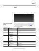
Planning the Kinetix 6000M System Installation Chapter 2 Table 7 - Power Dissipation Specifications - Percent of DC Bus Current Power Dissipation as % of DC Bus Current Output Rating Watts 20% 40% 60% 80% 100% Heat Dissipation Formula (1) 2 7 14 25 38 Y = 33.95x2 + 3.18x (1) x is percent of DC bus current output rating: any value between 0.0 and 1.0.
Chapter 2 Planning the Kinetix 6000M System Installation Figure 7 - Minimum IPIM Module Clearance Requirements 50.8 mm (2.0 in.) clearance for airflow and installation 287 mm (11.3 in.) (2) Clearance left of the module is not required (1) Clearance right of the module is not required (1) Power Rail (2094-PRSx) 50.8 mm (2.0 in.) clearance for airflow and installation (1) The power rail (slim), catalog number 2094-PRSx, extends left and right of the first and last module 5.0 mm (0.20 in.).
Planning the Kinetix 6000M System Installation Chapter 2 Figure 8 - Minimum IDM Unit Clearance Requirements 100.0 mm (3.9 in.) 100.0 mm (3.9 in.) 100.0 mm (3.9 in.
Chapter 2 Planning the Kinetix 6000M System Installation Figure 9 - Noise Zones (Bulletin 2094 power rail with IPIM module) Dirty Wireway D Clean Wireway Very Dirty Filter/IAM Connections Segregated (not in wireway) Motor and Hybrid Cables C D D VD Fiber-optic Cables and IPIM Communication Wires No sensitive (2) equipment within 150 mm (6.0 in.).
Chapter 3 Mounting the Kinetix 6000M System This chapter provides the system installation procedures for mounting your Kinetix 6000M integrated drive-motor (IDM) unit and your power interface module (IPIM). Topic Page Mounting the IPIM Module 30 Installing the IDM Unit 33 This procedure assumes you have prepared your panel, mounted your Bulletin 2094 power rail, and understand how to bond your system.
Chapter 3 Mounting the Kinetix 6000M System Mounting the IPIM Module Using the 2094 Mounting Brackets You can use Bulletin 2094 mounting brackets to mount the power rail or LIM module over the AC line filter. Refer to the 2094 Mounting Brackets Installation Instructions, publication 2094-IN008, when using mounting brackets with your system. Installing the 2094 Power Rail The Bulletin 2094 power rail comes in lengths to support one IAM module and up to seven additional modules.
Mounting the Kinetix 6000M System Chapter 3 Figure 10 - Module Mounting Order Example Highest Power Utilization Integrated Axis Module IMPORTANT IPIM Module Lowest Power Utilization Axis Modules Shunt Module Slot Filler Module The IAM must be positioned in the leftmost slot of the power rail. Position your other modules to the right of the IAM module. Mount modules according to power utilization (highest to lowest) from left to right starting with the highest power utilization.
Chapter 3 Mounting the Kinetix 6000M System Mount the IPIM Module All modules mount to the power rail using the same technique. 1. Determine the next available slot and module for mounting. Refer to Determine Mounting Order on page 30. 2. Remove the protective covers from the power rail connectors. 3. Inspect the module connector pins and power rail connectors and remove any foreign objects.
Mounting the Kinetix 6000M System Chapter 3 7. Tighten the mounting screws. Bracket secured in slot Flat 2.26 N•m (20 lb•in) Power Rail 8. Repeat the above steps for each module being installed. Installing the IDM Unit ATTENTION: Do not attempt to open or modify the IDM unit. This manual describes modifications that you can perform in the field. Do not attempt other changes. Only a qualified Allen-Bradley employee can service an IDM unit.
Chapter 3 Mounting the Kinetix 6000M System Aligning the IDM Unit The IDM unit can be mounted in any position and has a mounting pilot that aids in aligning the unit on a machine. A shaft seal that helps protect the motor against fine dust and fluids is factory installed and should be replaced at regular intervals. Preferred fasteners are stainless steel. The installation must comply with all local regulations.
Mounting the Kinetix 6000M System Chapter 3 1. Allow sufficient clearances around the IDM unit for it to stay within its specified operating temperature range. See page 27 for details. BURN HAZARD: Outer surfaces of the IDM unit can reach high temperatures, 125 °C (275 °F), during motor operation. Take precautions to prevent accidental contact with hot surfaces. Consider IDM unit surface temperature when selecting motor mating connections and cables.
Chapter 3 Mounting the Kinetix 6000M System Notes: 36 Rockwell Automation Publication 2094-UM003A-EN-P - May 2012
Chapter 4 Kinetix 6000M System Connector Data This chapter provides connector locations and signal descriptions for your Kinetix 6000M integrated drive-motor system.
Chapter 4 Kinetix 6000M System Connector Data IPIM Module Connectors and Indicators Figure 11 - Module Connectors and Indicators ➊ ➍ 1 SH + 42 2 SE SE N 1 SE T 3 SH RT OU + CN CN 2 SH 42 ➎ ➋ ➌ ➏ ➐ ➑ ETH ERNE T1 ETHERN ET 2 NETWO RK ➒ ➓ Item Description 38 See page ➊ Hybrid cable DC bus connector Termination point for +/- DC and PE 39 ➋ Hybrid cable communication signals connector Connection point for IDM unit power and communication 39 ➌ Safe-off connector Terminatio
Kinetix 6000M System Connector Data IPIM Module Connector and Signal Descriptions Hybrid Cable DC Bus Connector Chapter 4 1 DC- DC+ This connector supplies the DC bus voltage. Three wires from the hybrid power and communication cable (catalog number 2090CHBIFS8-12AAxx) are used to extend this voltage to the first IDM unit.
Chapter 4 Kinetix 6000M System Connector Data Safe Torque-off Connector This connector provides a termination point for connecting safety devices such as: emergency stop switches, light curtains, and floor mats. The redundant safety device outputs should be connected to Safety Enable Input 1 and 2 with reference to Safety Enable Common. F 2 +F2 F 1 +F1 S E 2S E S E 12 4 + 24- 1 Remove the motionallowed jumper before connecting any safety devices.
Kinetix 6000M System Connector Data Chapter 4 Sercos Fiber-optic Connectors The sercos fiber-optic ring is connected by using the sercos receive (RX) and transmit (TX) connectors. Receive Transmit ATTENTION: To avoid damage to the sercos RX and TX connectors use only finger-tight torque when attaching the fiber-optic cables. Do not use a wrench or any other mechanical assistance. For more information, refer to Fiber-optic Cable Installation and Handling Instructions, publication 2090-IN010.
Chapter 4 Kinetix 6000M System Connector Data EtherNet/IP Connectors Two connectors are provided for firmware upgrades, troubleshooting, and integration with Logix. The Ethernet ports also support a web browser interface to provide access to status information for the IPIM module and IDM units.
Kinetix 6000M System Connector Data Figure 12 - Integrated Drive-motor Unit Features, Connectors, and Indicators ➊ ➋ ➍ ➏ ➎ ➌ 456 90 1 78 23 D ➐ N S1 456 90 1 78 S10 1 23 IDM Unit Connectors and Indicators Chapter 4 2 3 ➓ ➒ ➑ Item Description ➊ Hybrid cable input connector (from IPIM module or previous IDM unit) ➋ Hybrid cable output connector (to IDM unit) ➌ IDM network output connector (to IDM unit) ➍ IDM network input connector (from IPIM module or previous IDM unit) ➎ See p
Chapter 4 Kinetix 6000M System Connector Data IDM Unit Connector and Signal Descriptions Hybrid Cable Connector The information below provides connector pinouts for the IDM unit hybrid connectors.
Kinetix 6000M System Connector Data Chapter 4 IDM Network Input and Output Connector Pinouts Pinout information is provided below for the IDM unit network connectors.
Chapter 4 Kinetix 6000M System Connector Data IDM units have three 5-pin, M12, digital input connectors. Allen-Bradley (Bulletin 889D) DC micro-style patchcords, splitters, and V-cables are available with straight and right-angle connectors for making connections from the IDM unit to input sensors. For the most popular patchcord specifications, refer to the Connection Systems Quick Selection Guide, publication CNSYS-BR001.
Kinetix 6000M System Connector Data Chapter 4 Single Normally Open (NO) Sensor Connection Normally open sensors are used for registration or home switches on the IDM unit. Any 4-pin or 5-pin, M12, A-code, 1-1 pass through cable can be used to connect a normally open sensor. Refer to Figure 14.
Chapter 4 Kinetix 6000M System Connector Data Digital Input Cable Examples Figure 16 - Digital Inputs Used for Home and Overtravel Functions MDF-SBxxxxx IDM Units D N D S1 S10 N S1 1 Digital Inputs (1, 2, 3) 3 2 S10 1 3 2 889D-x4ACDx-xx Patchcords Input Assignments: 1 = Overtravel- (NC) 2 = Overtravel+ (NC) 3 = Home (NO) Input Assignments: 1 = Registration 2 (NO) 2 = Registration 1 (NO) 871TS-N12BP18-D4 Proximity Sensors 1 2 3 1 2 Figure 17 - Digital Inputs Used for Home, Overtravel
Kinetix 6000M System Connector Data Chapter 4 Table 14 - Understanding the Digital Inputs Pin Connector Signal Description Capture Edge/Level Time Sensitive 4 1 HOME Optically isolated, single-ended active high signal. Current loading is nominally 10 mA. Home switch (normally open contact) inputs for each axis require 24V DC (nominal).
Chapter 4 Kinetix 6000M System Connector Data Power Specifications Brake Override Input ATTENTION: To guard against personal injury and/or component damage, the brake override must only be used for machine assembly when the IPIM module is not connected to the IDM unit. The brake override connection is made on two dedicated pins of the hybrid input connector. The hybrid cable has no connection on those pins. The brake override may only be activated when the hybrid input cable is not connected.
Kinetix 6000M System Connector Data Chapter 4 MDF-1003 Peak Inverter Overload (TPK < 2.0 s) 35% Ipk = 200% Ipk = 350% Ipk = 471% Maximum Duty Cycle (Dmax) 30% 25% 20% 15% 10% 5% 0% 0% 20% 40% 60% 80% 100% % Base Current (IBase/Icont) MDF-1153 Peak Inverter Overload (TPK < 2.0 s) 35% Ipk = 200% Ipk = 350% Ipk = 443% Maximum Duty Cycle (Dmax) 30% 25% 20% 15% 10% 5% 0% 0% 20% 40% 60% 80% 100% % Base Current (IBase/Icont) MDF-1304 Peak Inverter Overload (TPK < 2.
Chapter 4 Kinetix 6000M System Connector Data Feedback Specifications Kinetix 6000M integrated drive-motors are available with high performance digital encoders with multi-turn high resolution feedback: • 524,288 counts per revolution • High-resolution absolute position feedback within 4096 turns. The IDM unit does not support an auxiliary feedback device.
Chapter 5 Connecting the Kinetix 6000M System This chapter provides procedures for wiring the integrated drive-motor system components. Basic Wiring Requirements Topic Page Basic Wiring Requirements 53 Grounding the IDM System 54 General IDM System Wiring 56 How to Bypass an IDM Unit 58 The Sercos Fiber-optic Ring 59 Ethernet Cable Connections 63 This section contains basic wiring information for the Kinetix 6000M integrated drive-motor system.
Chapter 5 Connecting the Kinetix 6000M System IMPORTANT IDM system wiring differs from common PWM servo system wiring configurations in the following ways: • Hybrid and network cables can be tie-wrapped together and occupy the same cable run • Hybrid and network cables do not require physical segregation as a result of more effective wire shielding and improved grounding techniques.
Connecting the Kinetix 6000M System Chapter 5 Signal integrity is very important for successful operation of an integrated drivemotor system. You must be sure that all cables are properly grounded through the IPIM module to the ground plane of the Kinetix drive system. • Verify that every cable shield directly connects to chassis ground. • Clamp the exposed section of the hybrid cable shield in the cable (chassis) ground connection on the drive. Refer to Apply the Cable Shield Clamp.
Chapter 5 Connecting the Kinetix 6000M System General IDM System Wiring ATTENTION: Arcing or unexpected motion can occur if cables are connected or disconnected while power is applied to the IDM system. Before working on the system, disconnect power and wait the full time interval indicated on the IPIM module warning label or verify the DC bus voltage at the IPIM module measures less than 50V DC.
Connecting the Kinetix 6000M System Chapter 5 Figure 22 - IDM System Wiring (Catalog numbers are in parenthesis.
Chapter 5 Connecting the Kinetix 6000M System Figure 24 - Hybrid Cable Installed Hybrid Cable DC Bus Connector Hybrid Cable 42+ 42SH2 CNCN+ OUT RTN SH3 SE1 SESE2 Hybrid Cable Communication Signals Connector Network Cable The IDM system network is routed by using 2090-CNSxPxS-AAxx cables. A 2090-CNSSPRS-AAxx or 2090-CNSSPSS-AAxx cable is required for connection to the IPIM module. 2090-CNSSPRS-AAxx 2090-CNSRPSS-AAxx(1) 2090-CNSRPRS-AAxx(1) 2090-CNSSPSS-AAxx (1) Not for connection to an IPIM module.
Connecting the Kinetix 6000M System The Sercos Fiber-optic Ring Chapter 5 The sercos fiber-optic ring is connected by using the sercos receive (RX) and transmit (TX) connectors. Refer to Sercos Fiber-optic Connectors on page 41 for details. Refer to the documentation supplied with your Logix sercos interface module or PCI card for connector locations. Plastic cable is available in lengths up to 32 m (105.0 ft). Glass cable is available in lengths between 50 m (164.2 ft) and 200 m (656.7 ft).
Chapter 5 Connecting the Kinetix 6000M System In this five-axis Bulletin 2094 power rail configuration, the IAM module and two AM modules power three of the axes and two IPIM modules are each connected to four IDM units. All eleven axes are on the same sercos ring. It is not required that all Kinetix 6000 drives be on the same sercos ring; however, it is required that all IDM units be on the same sercos ring as the IPIM module they are connected to.
Connecting the Kinetix 6000M System Chapter 5 This configuration has the same drive modules and IPIM modules as shown in Figure 26, except the five modules are split between two sercos rings. Each ring has its own 1756-M08SE sercos module in the ControlLogix controller chassis. It is not required that all Kinetix 6000 drives be on the same sercos ring; however, it is required that all IDM units be on the same sercos ring as the IPIM module they are connected to.
Chapter 5 Connecting the Kinetix 6000M System In this configuration, the 8-axis Bulletin 2094 power rail has four drive modules and four IPIM modules. Each IPIM module is connected to four IDM units. There are five sercos rings and each ring has its own 1756-M08SE sercos module in the ControlLogix controller chassis. It is not required that all Kinetix 6000 drives be on the same sercos ring; however, it is required that all IDM units be on the same sercos ring as the IPIM module they are connected to.
Connecting the Kinetix 6000M System Ethernet Cable Connections Chapter 5 This procedure assumes you have your ControlLogix or CompactLogix EtherNet/IP module and Bulletin 2094 control modules mounted and are ready to connect the Ethernet network cables. The EtherNet/IP network is connected by using the PORT 1 and/or PORT 2 connectors. The IPIM module uses the EtherNet/IP network only for configuring the Logix program. Refer to page 42 to locate the Ethernet connector on your IPIM module.
Chapter 5 Connecting the Kinetix 6000M System Notes: 64 Rockwell Automation Publication 2094-UM003A-EN-P - May 2012
Chapter 6 Configuring the Kinetix 6000M System This chapter provides procedures for configuring your Kinetix 6000M system components with your Logix sercos module.
Chapter 6 Configuring the Kinetix 6000M System Understanding the IPIM Module Display The IPIM module has six status indicators (see Interpret Status Indicators on page 90) and a four-line LCD display. The indicators and display are used to monitor the system status, set network parameters, and troubleshoot faults. Four navigation buttons are located directly below the display and are used to select items from a soft menu.
Configuring the Kinetix 6000M System Chapter 6 Startup Sequence On initial powerup, the IPIM module performs a self test of the system. Upon successful completion, the following confirmation is displayed, followed by the firmware version and IP address. Running Self Tests . . . OK FW Version 1.xx.xx IP Address: 192.169.1.111 Next, the home screen displays the address of each connected IDM unit.
Chapter 6 Configuring the Kinetix 6000M System The following information is displayed. IPIM Information IDM Information Module Status: - IP Address - OK -Standby (OK, but no CIP connection) -Faulted -Init Fault (Requires reboot) Status: Displays IDM status values. Bus Reg Cap Percent of shunt capacity being utilized. Safety: “Motion-allowed” or “Safe-off.” Active Faults: Active faults (one per line) will be displayed. Sercos Phase: Current sercos phase of the IDM: 0 -5.
Configuring the Kinetix 6000M System Configuring the IPIM Module Chapter 6 You can include the IPIM module in your RSLogix 5000 project by connecting it to a configured Ethernet module in the Logix chassis and adding it under the Ethernet module in the I/O configuration tree. As a result, you can view the IPIM module status information in RSLogix 5000 software and use it in your Logix program. To select the IPIM module in RSLogix 5000 software, version 20, you must load an Add-on Profile (see page 73).
Chapter 6 Configuring the Kinetix 6000M System Configuring the IDM Unit Setting the Node Address The node address is set by switches on each IDM unit. This address is the actual sercos node address, not an offset from the IAM module. The address is read at power up, so if the switch settings are changed while power is applied, the changes do not take effect until the next power cycle. Refer to Figure 31 and remove the two protective covers to gain access to the switches.
Configuring the Kinetix 6000M System Chapter 6 In the following example (Figure 32), the Kinetix 6000 power rail contains two single-wide axis modules and one IDM system. A sercos node address is not assigned to the slot-filler or the IPIM module. However, the system identifies both modules with slot locations. Node addresses 02 and 05 are available for any of the IDM units, but to avoid confusion, the node addressing for the IDM units was started at 20.
Chapter 6 Configuring the Kinetix 6000M System In example 2 (Figure 33), the Kinetix 6000 power rail contains two single-wide axis modules and two IDM systems. A sercos node address is not assigned to the slot-filler or the IPIM module, but the system identifies both with slot locations. Node addressing for the IDM system example 2 is similar to the first. Each IDM unit has switches that determine its node address. In this example, the IDM unit node addressing starts at 30 and is sequential.
Configuring the Kinetix 6000M System Add-on Profiles Chapter 6 To select the IPIM module in RSLogix 5000 software, version 20, you must load an Add-on Profile from www.ab.com. To navigate to the Add-on Profiles, follow this path: • Technical Support • Software Updates, Firmware and Other Downloads • RSLogix 5000 I/O Modules Add-On-Profiles You will be required to establish a login and provide the serial number of your drive to access the download file.
Chapter 6 Configuring the Kinetix 6000M System a. b. c. d. e. From the Type pull-down menu, choose the controller type. From the Revision pull-down menu, choose the revision (V20). Type the file Name. From the Chassis Type pull-down menu, choose the chassis. Enter the Logix processor slot. 4. Click OK. 5. From the Edit menu, choose Controller Properties. The Controller Properties dialog box opens. 6. Click the Date/Time tab. 7. Check Enable Time Synchronization.
Configuring the Kinetix 6000M System Chapter 6 Configure the Logix Module Follow these steps to configure the Logix module. 1. Right-click I/O Configuration in the Controller Organizer and choose New Module. The Select Module dialog box opens. 2. Scroll to select the sercos module as appropriate for your actual hardware configuration. In this example, the 1756-M16SE module is selected. 3. Click Create. The New Module dialog box opens. 4. Configure the new module. a. Type the module Name. b.
Chapter 6 Configuring the Kinetix 6000M System TIP The IDM system data rate is fixed at 8 Mbps. 6. Verify that the data rate DIP switches on the IAM module and any AM modules on the same sercos ring are set to 8 Mbps. 7. Click the SERCOS Interface tab. 8. From the Data Rate pull-down menu choose 8 Mb or choose the Auto Detect setting. 9. From the Cycle Time pull-down menu, choose the Cycle Time according to the table below. Data Rate 8 Mbps (1) Number of Axes Cycle Time Up to 4 0.
Configuring the Kinetix 6000M System Chapter 6 Configure the IDM Units Follow these steps to configure the IDM units. 1. Right-click the Logix module you just created and choose New Module. The Select Module dialog box opens. 2. Scroll to select the IDM unit appropriate for your actual hardware configuration. IMPORTANT To configure IDM units (catalog numbers MDF-SBxxxxx) you must be using RSLogix 5000 software, version 20.01 or later. Version 20.00 can be used if the motion database has been updated.
Chapter 6 Configuring the Kinetix 6000M System 6. Click the Associated Axes tab. 7. Click New Axis. The New Tag dialog box opens. 8. Type the axis Name. AXIS_SERVO_DRIVE is the default Data Type. 9. Click Create. The axis appears under the Ungrouped Axes folder in the Controller Organizer. 10. Assign your axis to Node 1. TIP Auxiliary feedback is not supported by the IDM units. 11. Click OK. 12. Repeat step 1 through step 11 for each IDM unit.
Configuring the Kinetix 6000M System Chapter 6 Configure the Motion Group Follow these steps to configure the motion group. 1. Right-click Motion Groups in the Controller Organizer and choose New Motion Group. The New Tag dialog box opens. 2. Type the new motion group Name. 3. Click OK. The new motion group appears under the Motion Groups folder. 4. Right-click the new motion group and choose Properties. The Motion Group Properties dialog box opens. 5.
Chapter 6 Configuring the Kinetix 6000M System Configure Axis Properties Follow these steps to configure the Axis properties. 1. Right-click an axis in the Controller Organizer and choose Properties. The Axis Properties dialog box opens. 2. On the Drive/Motor tab, check Drive Enable Input Checking. When checked (default), means a hard drive-enable input signal is required. Uncheck to remove that requirement. TIP The drive-enable input signal is located on the IPIM module. 3. Click Apply. 4.
Configuring the Kinetix 6000M System Chapter 6 8. Click the Fault Actions tab. 9. Click Set Custom Stop Action. The Custom Stop Action Attributes dialog box opens and lets you set delay times for IDM units. 10. Configure the delay times. a. Type the Brake Engage Delay Time. b. Type the Brake Release Delay Time. Cat. No. Brake Engage Delay ms Brake Release Delay ms MDF-SB1003 20 50 25 110 MDF-SB1153 MDF-SB1304 c. Click Close. 11. Click OK. 12. Repeat step 1 through step 11 for each IDM unit. 13.
Chapter 6 Configuring the Kinetix 6000M System Apply Power to the System This procedure assumes that you have wired and configured your Kinetix drive system (with or without the LIM module) and your sercos interface module. ATTENTION: Capacitors on the DC bus may retain hazardous voltages after input power has been removed.
Configuring the Kinetix 6000M System Test and Tune the Axes Chapter 6 This procedure assumes that you have configured your Kinetix 6000M system, your Logix sercos interface module, and applied power to the system. For help using RSLogix 5000 software as it applies to testing and tuning your axes with ControlLogix, CompactLogix, or SoftLogix sercos modules, refer to Additional Resources on page 7. Test the Axes Follow these steps to test the axes. 1. Verify the load was removed from each axis. 2.
Chapter 6 Configuring the Kinetix 6000M System 6. Select the desired Test (Marker/Feedback/Command & Feedback) to verify connections. The Online Command dialog box opens. Follow the on-screen test instructions. When the test completes, the Command Status changes from Executing to Command Complete. 7. Click OK. The Online Command - Apply Test dialog box opens (Feedback and Command & Feedback tests only). When the test completes, the Command Status changes from Executing to Command Complete. 8. Click OK.
Configuring the Kinetix 6000M System Chapter 6 Tune the Axes Follow these steps to tune the axes. 1. Verify the load is still removed from the axis being tuned. ATTENTION: To reduce the possibility of unpredictable motor response, tune your motor with the load removed first, then re-attach the load and perform the tuning procedure again to provide an accurate operational response. 2. Click the Tune tab. 3. Type values for Travel Limit and Speed. In this example, Travel Limit = 5 and Speed = 10.
Chapter 6 Configuring the Kinetix 6000M System 8. Click OK. The Tune Bandwidth dialog box opens. Actual bandwidth values (Hz) depend on your application and may require adjustment once motor and load are connected. 9. Record your bandwidth data for future reference. 10. Click OK. The Online Command - Apply Tune dialog box opens. When the test completes, the Command Status changes from Executing to Command Complete. 11. Click OK. 12. Determine if your test completed successfully.
Chapter 7 Troubleshooting the Kinetix 6000M System Safety Precautions Topic Page Safety Precautions 87 IDM System Error Codes 87 Interpret Status Indicators 90 General System Anomalies 92 IPIM Module Fault Diagnosis 93 IDM Unit Fault Diagnosis 95 Use a Web Browser to Monitor System Status 97 ATTENTION: Capacitors on the DC bus may retain hazardous voltages after input power has been removed.
Chapter 7 Troubleshooting the Kinetix 6000M System Connecting the IPIM module into the Logix environment as an EtherNet/IP device does not disable fault reporting through the IAM module. Only the IAM fault reporting lets the Logix motion sub-system take action based on the IPIM module fault status. IPIM faults are also reported to Logix over the Ethernet connection. However, IPIM faults must be reset by applying a fault reset instruction to the IAM module.
Troubleshooting the Kinetix 6000M System Chapter 7 Figure 34 - Message Configuration - Write 1. Set the Source field to a tag that contains the slot location for the IPIM module. The slot location valid range is 2 - 8, (assuming an 8 slot power rail). The IAM module is always in slot 1. 2. Set the path field on the communication tab to the IAM module on the power rail where the IPIM module is located. Set the read message configuration parameters as shown Figure 35.
Chapter 7 Troubleshooting the Kinetix 6000M System Interpret Status Indicators When a fault condition is detected, the appropriate status indicator will illuminate (IDM unit or IPIM module) and the IPIM module will annunciate the fault on its front panel display. Refer to Figure 36 for IPIM status indicator descriptions and Figure 37 for IDM unit indicators. IPIM Module Status Indicators IPIM module fault descriptions, types and actions start on page 94.
Troubleshooting the Kinetix 6000M System Indicator Port 1 Port 2 Status of the EtherNet/IP ports Chapter 7 Indication Description Off Port is not connected Flashing Green Port is connected and communication is occurring Solid Green Port is connected, but no communication is not occurring (1) A reset or cycling the power may clear a recoverable fault (depending on the state of the IDM).
Chapter 7 Troubleshooting the Kinetix 6000M System General System Anomalies These anomalies do not always result in a fault code, but may require troubleshooting to improve performance. Condition Potential Cause Possible Solution Axis or system is unstable. Unintentionally in Torque mode. Check to see what primary operation mode was programmed. IDM unit tuning limits are set too high. Run Tune in RSLogix 5000 software. Position loop gain or position controller accel/decel rate is improperly set.
Troubleshooting the Kinetix 6000M System Condition Potential Cause Possible Solution No rotation The IDM unit connections are loose or open. Check IDM unit wiring and connections. Foreign matter is lodged in the IDM unit. Remove foreign matter. The IDM unit load is excessive. Verify the servo system sizing. The bearings are worn. Return the IDM unit for repair. The IDM unit brake is engaged (if supplied). • Check brake wiring and function. • Return the IDM unit for repair.
Chapter 7 Troubleshooting the Kinetix 6000M System IPIM Module Fault Types The IPIM has two fault types: resettable and non-resettable. When an IPIM module fault occurs, the fault is reported to the IAM module. The IAM module reports an IPIM fault to the Logix controller. Resettable faults - when the IPIM module fault is cleared from the IAM module, the fault is removed from its display (if the condition has been removed).
Troubleshooting the Kinetix 6000M System IDM Unit Fault Diagnosis Chapter 7 Logix Controller/IDM Unit Fault Behavior These RSLogix 5000 fault actions are configurable from the Axis Properties dialog box, Fault Actions tab. Table 21 - Fault Action Definitions Fault Action Definition Shutdown Axis is disabled as defined in Table 22. In addition, the axis in Logix enters the Shutdown state, which disables any axes that are using this axis as a camming or gearing master.
Chapter 7 Troubleshooting the Kinetix 6000M System Table 22 - Exception/Fault Behavior (continued) RSLogix Programmable Fault Action Fault Behavior IPIM Display (RSLogix Drive Fault) IDM Status Indicator Potential Cause Possible Solution E06 – Positive/Negative Hard Overtravel (Pos/NegHardOvertravelFault) Flashing Red Axis moved beyond the physical travel limits in the positive/negative direction. • Verify motion profile. • Verify axis configuration in software.
Troubleshooting the Kinetix 6000M System Chapter 7 Table 22 - Exception/Fault Behavior (continued) RSLogix Programmable Fault Action Fault Behavior IPIM Display (RSLogix Drive Fault) IDM Status Indicator Potential Cause E66 – Autotune (DriveHardFault) Flashing Red Autotune procedure failed. • Check IDM unit power/feedback wiring. • Refer to RSLogix 5000 on-screen message for resolution. • Perform Hookup Test in RSLogix 5000 software. • Consult RSLogix 5000 help screen.
Chapter 7 Troubleshooting the Kinetix 6000M System To access the web interface: 1. Using an Ethernet cable, connect your computer to one of the Ethernet ports on the IPIM module (refer to Figure 11 on page 38 for location). 2. Open a web browser program(1) and enter the IP address of the IPIM module. The Home screen will be displayed. 3. Selecting IPIM Indicators provides indicator status. 4. Network settings displays a summary of the various parameters. (1) Internet Explorer version 6.
Chapter 8 Removing and Replacing the Kinetix 6000M IPIM Module This chapter provides removal and replacement procedures for your Kinetix 6000M IPIM module. Refer to your Kinetix 6000 Multi-axis Servo Drives User Manual, publication 2094-UM001, or Kinetix 6200 and Kinetix 6500 Modular Multi-axis Servo Drives User Manual, publication 2094-UM002, for other replacement procedures.
Chapter 8 Removing and Replacing the Kinetix 6000M IPIM Module Remove the IPIM Module Follow these steps to remove your IPIM module from the Bulletin 2094 power rail. 1. Verify that all control and input power has been removed from the system. ATTENTION: To avoid shock hazard or personal injury, assure that all power has been removed before proceeding. This system may have multiple sources of power. More than one disconnect switch may be required to de-energize the system. 2.
Removing and Replacing the Kinetix 6000M IPIM Module Chapter 8 7. Lift the bracket out of the power rail slot and remove the module from the power rail. Power Rail Guide Pin Fuse Pivot Module Upward ss Acce er See Us ving e Remo al Befor Manu Side View Replace the IPIM Module Follow these steps to replace the IPIM module on the Bulletin 2094 power rail. 1. Inspect the module connector pins and power rail connectors and remove any foreign objects. 2.
Chapter 8 Removing and Replacing the Kinetix 6000M IPIM Module Notes: 102 Rockwell Automation Publication 2094-UM003A-EN-P - May 2012
Appendix A Using the Safe Torque-off Feature with the Kinetix 6000M System This appendix introduces you to how the safe torque-off feature meets the requirements of Performance Level d (PLd) and Category 3 (Cat3) per EN ISO 13849-1 and SIL CL 2 per IEC EN 61508, EN 61800-5-2 and EN 62061.
Appendix A Using the Safe Torque-off Feature with the Kinetix 6000M System Category 3 Requirements According to EN ISO 13849-1 Safety-related parts are designed with these attributes: • A single fault in any of these parts does not lead to the loss of the safety function • A single fault is detected whenever reasonably practicable • Accumulation of undetected faults can lead to the loss of the safety function, which results in failure to remove motion producing power from the motor.
Using the Safe Torque-off Feature with the Kinetix 6000M System Appendix A ATTENTION: Permanent magnet motors may, in the event of two simultaneous faults in the IGBT circuit, result in a rotation of up to 180 electrical degrees. ATTENTION: If any of the safety enable inputs de-energize, then the SafeOffModeActiveStatus bit of the drive status word in the Axis Tag structure will be set to 1. It will reset to 0 when both safety enable inputs are energized within 1 second (see Figure 39).
Appendix A Using the Safe Torque-off Feature with the Kinetix 6000M System Figure 40 demonstrates when the safe torque-off mismatch is detected and a DriveHardFault is posted. Figure 40 - System Operation in the Event that the Safety Enable Inputs Mismatch 24V DC SAFETY ENABLE1+ 0V DC 24V DC SAFETY ENABLE2+ 0V DC 1 DriveHardFault 0 1 1 Second SafeOffModeActiveStatus 0 When one safety input is turned off, the second input must also be turned off, otherwise a fault is asserted (see Figure 41).
Using the Safe Torque-off Feature with the Kinetix 6000M System PFD, PFH, and MTTFd Definitions Appendix A Safety-related systems can be classified as operating in either a Low Demand mode, or in a High Demand/Continuous mode: • Low Demand mode: where the frequency of demands for operation made on a safety-related system is no greater than one per year or no greater than twice the proof-test frequency.
Appendix A Using the Safe Torque-off Feature with the Kinetix 6000M System European Union Directives If this product is installed within the European Union or EEC regions and has the CE mark, the following regulations apply. CE Conformity Conformity with the Low Voltage Directive and Electromagnetic Compatibility (EMC) Directive is demonstrated by using harmonized European Norm (EN) standards published in the Official Journal of the European Communities.
Using the Safe Torque-off Feature with the Kinetix 6000M System Appendix A Refer to the Kinetix Safe-off Feature Safety Reference Manual, publication GMC-RM002, for wiring examples. ATTENTION: This option may be suitable for performing mechanical work on the drive system or affected area of a machine only. It does not provide electrical safety. SHOCK HAZARD: In Safe Torque-off mode, hazardous voltages may still be present at the IDM unit.
Appendix A Using the Safe Torque-off Feature with the Kinetix 6000M System Figure 42 - Typical Kinetix 6000M and Kinetix 6000 Safe-off Configuration Safe-off Control Circuit Connections Middle-drive Headers (2090-XNSM-M) Last-drive Header (2090-XNSM-T) First-drive Wiring Header (2090-XNSM-W) Drive-to-Drive Safe-off Cables 1202-C02 System 1 Kinetix 6000 and Kinetix 6000M Systems 1202-C03 1202-C02 IPIM to IDM Hybrid Cable (2090-CHBIFS8-12AAxx) IDM Unit Network Cable (2090-CNSxPxS) 1202-C03 Syste
Using the Safe Torque-off Feature with the Kinetix 6000M System Safe Torque-off Signal Specifications Appendix A This table provides specifications for the safe torque-off signals used. Attribute Safety inputs Value Input current less than10 mA Input ON voltage range 18…26.
Appendix A Using the Safe Torque-off Feature with the Kinetix 6000M System Notes: 112 Rockwell Automation Publication 2094-UM003A-EN-P - May 2012
Appendix B Interconnect Diagram This appendix provides a wiring example for the IDM system.
Appendix B Interconnect Diagram Figure 43 - IPIM Module and IDM Unit Wiring Example MDF-SBxxxxx-Qx8xA-S Kinetix 6000M IDM Unit 2094-SEPM-B24-S Kinetix 6000M IPIM Module Cable Shield Clamp 2090-CHBIFS8-12AAxx Hybrid Cable DC Bus Connector Inter-module Communication Connector DCDC+ SH1 42+ 42SH2 CNCN+ OUT RTN SH3 SE1 SESE2 1 2 3 Grey Green Brown 2 3 4 5 6 7 8 9 10 11 12 Blue White/Blue Drain White/Brown Brown White/Pink Pink Drain Orange Violet Yellow Hybrid Cable Input Connector Hybrid Cable Out
Appendix C Upgrading the Kinetix 6000M System Firmware This appendix provides procedures for upgrading firmware for the Kinetix 6000M integrated drive-motor (IDM) units and IDM power interface modules (IPIM). Topic Page Before You Begin 115 Configure Logix Communication 116 IPIM Module Firmware Upgrade 117 IDM Unit Firmware Upgrade 122 Verify the Firmware Upgrade 126 Upgrading firmware for the Kinetix 6000M system is done by using ControlFLASH software.
Appendix C Upgrading the Kinetix 6000M System Firmware Configure Logix Communication This procedure assumes that your communication method to the Logix controller is using the Ethernet protocol. It is also assumed that your Logix Ethernet module has already been configured. For more information, refer to the ControlLogix System User Manual, publication 1756-UM001. Follow these steps to configure Logix communication. 1. Open your RSLinx Classic software. 2.
Upgrading the Kinetix 6000M System Firmware Appendix C 8. Click OK. The new Ethernet driver appears under Configured Drivers. 9. Click Close. 10. Minimize the RSLinx application dialog box. IPIM Module Firmware Upgrade IMPORTANT The IPIM module will not accept a firmware upgrade request when it has an active CIP I/O connection. An active CIP I/O connection exists when the IPIM module has been integrated into the I/O configuration tree in RSLogix 5000 software.
Appendix C Upgrading the Kinetix 6000M System Firmware Follow these steps to select the IPIM module to upgrade. 1. Make sure the IPIM module will accept a firmware request prior to attempting the firmware upgrade (see page 117). 2. Open your ControlFLASH software. You can access the ControlFLASH software by either of these methods: • From the Tools menu in RSLogix 5000 software, choose ControlFLASH. • Choose Start>Programs>FLASH Programming Tools> ControlFLASH.
Upgrading the Kinetix 6000M System Firmware Appendix C The Select Device to Update dialog box opens. 6. Expand your Ethernet node and EtherNet/IP network module. 7. Select the IPIM module to upgrade. 8. Click OK. The Firmware Revision dialog box opens. 9. Select the firmware revision to upgrade. 10. Click Next.
Appendix C Upgrading the Kinetix 6000M System Firmware The Summary dialog box opens. 11. Confirm the IPIM module catalog number and firmware revision. 12. Click Finish. This ControlFLASH warning dialog box opens. 13. Click Yes (only if you are ready). This ControlFLASH warning dialog box opens. 14. Acknowledge the warning and click OK.
Upgrading the Kinetix 6000M System Firmware Appendix C The Progress dialog box opens and upgrading begins. After the upgrade information is sent to the IPIM module, the module resets and performs diagnostic checking. 15. Wait for the Progress dialog box to time out. It is normal for this process to take several minutes. IMPORTANT Do not cycle power to the drive during this process or the firmware upgrade will not complete successfully. 16.
Appendix C Upgrading the Kinetix 6000M System Firmware IDM Unit Firmware Upgrade Follow these steps to select the IDM unit to upgrade. 1. Open your ControlFLASH software. You can access the ControlFLASH software by either of these methods: • From the Tools menu in RSLogix 5000 software, choose ControlFLASH. • Choose Start>Programs>FLASH Programming Tools> ControlFLASH. The Welcome to ControlFLASH dialog box opens. 2. Click Next. The Catalog Number dialog box opens. 3. Select your IDM unit. 4.
Upgrading the Kinetix 6000M System Firmware Appendix C The Select Device to Update dialog box opens. 5. Expand your Ethernet node, Logix backplane, and EtherNet/IP network module. 6. Select the IDM unit to upgrade. 7. Click OK. The Firmware Revision dialog box opens. 8. Select the firmware revision to upgrade. 9. Click Next.
Appendix C Upgrading the Kinetix 6000M System Firmware The Summary dialog box opens. 10. Confirm the IDM unit catalog number and firmware revision. 11. Click Finish. This ControlFLASH warning dialog box opens. 12. Click Yes (only if you are ready). This ControlFLASH warning dialog box opens. 13. Acknowledge the warning and click OK.
Upgrading the Kinetix 6000M System Firmware Appendix C The Progress dialog box opens and upgrading begins. After the upgrade information is sent to the IDM unit, the unit resets and performs diagnostic checking. 14. Wait for the Progress dialog box to time out. It is normal for this process to take several minutes. IMPORTANT Do not cycle power to the drive during this process or the firmware upgrade will not complete successfully. 15.
Appendix C Upgrading the Kinetix 6000M System Firmware Verify the Firmware Upgrade Follow these steps to verify your firmware upgrade was successful. This procedure uses an IDM unit as an example, but applies to IPIM modules too. TIP Verifying the firmware upgrade is optional. 1. Open your RSLinx software. 2. From the Communications pull-down menu, choose RSWho. 3. Expand your Ethernet node, Logix backplane, and EtherNet/IP network module. 4.
Appendix D Kinetix 6000M System Sizing It is recommended that Motion Analyzer (version 6.000 or greater), be used for sizing your system. If manual calculation is desired, the following procedure can be used. Definitions Topic Page Definitions 127 Manually Sizing the Kinetix 6000M System 128 • Control power = 120/240 single-phase AC voltage connected to the IAM unit. • IDM system control power = 42V DC (nominal) voltage from the IPIM module that is connected to all IDM units.
Appendix D Kinetix 6000M System Sizing Manually Sizing the Kinetix 6000M System Step 1: Calculate the IDM unit control power load current for each IDM unit. There are three components to the control power load current for each IDM unit: • Constant power load • Digital input loads • Brake loads Refer to the IDM unit constant load, brake load, and control power load specifications shown below. IDM Unit Cat. No.
Kinetix 6000M System Sizing Appendix D Example Example System: • Common bus leader IAM module • Two AM modules • One IPIM module • Six IDM units (shown below) • 72 total meters of hybrid cable • Control power = 120V AC, 60 Hz • Main power = 480V AC => 675V DC For this example, assume that each digital input uses 50 mA at 24V DC. IDM Unit Cat. No. Digital Inputs with Brake Constant Load (W) Dig Input Load (W) Brake Load (W) Total Load (W) MDF-SB1153 2 Yes 8 3.0 19.5 30.
Appendix D Kinetix 6000M System Sizing It is important to understand that each IDM unit passes the load current for all IDM units farther down the daisy chain. The voltage applied at each IDM unit is dependent on voltage drop in the IDM unit control power conductors of the hybrid cable. Therefore, the total cable length between an IDM unit and the IPIM module affect the voltage applied to that IDM unit.
Kinetix 6000M System Sizing Appendix D • Dividing the total IDM unit load power by 42V DC assumes that all the IDM units are at the IPIM module and experience no voltage drop from the hybrid cable. This is a very liberal method that always results in an underestimate of the load current. • Dividing the total IDM unit load power by 37V DC represents more of an average situation where all the IDM units experience half the maximum voltage drop. This is a reasonable compromise between the other two extremes.
Appendix D Kinetix 6000M System Sizing Step 3: Confirm that all IDM units connected to each IPIM module will have sufficient control power voltage. This is a complicated calculation to do accurately for the same reasons stated in step 2. The purpose of this step is to confirm that the last IDM unit in the daisy chain has sufficient voltage to operate. An estimate of the applied voltage assuming all the IDM units are at the end of the total cable length can be calculated as shown below.
Kinetix 6000M System Sizing Appendix D Example The equations in step 3 are applied to augment the table from the previous step (shown below). The estimate of the voltage assuming all IDM units are at the end of the total cable length is included in the last column. Average IDM Unit Control Power Voltage Estimate (VDC) IDM Unit Control Power Load Current (A) Voltage Estimate at Last (all) IDM Unit(s) 32 3.05 36.0 37 2.64 36.8 42 2.32 37.
Appendix D Kinetix 6000M System Sizing Table 24 - Max Cable Length per IPIM Module using Motion Analyzer (no digital inputs) 110 100 1 2 3 4 5 6 7 8 9 10 11 12 13 14 15 16 0 25 50 75 100 100 100 100 100 100 100 100 100 100 100 100 100 1 25 50 75 100 100 100 100 100 100 100 100 100 100 100 100 100 50 75 100 100 100 100 100 100 100 100 100 100 100 100 100 75 100 100 100 100 100 100 100 100 100 100 100 100 100 100 100 100 100
Kinetix 6000M System Sizing Appendix D Step 4: Estimate the IAM control power load current and the power dissipation for each IPIM module based on the total IDM unit control power load. See the Kinetix Rotary Motion Specifications Technical Data, publication GMC-TD001, for specifications on IPIM module dissipation and IPIM module control power loading. This information is also shown below.
Appendix D Kinetix 6000M System Sizing Step 5: Sum the IAM control power load current for all devices on the power rail and confirm that the total IAM control power load current is less than the specified IAM and power rail limit. • Calculate the total IAM control power load current by summing the load current calculated in step 4 for all IPIM modules.
Kinetix 6000M System Sizing Appendix D Step 6: Determine if a LIM can be used to supply the IAM control power load current, or if individual discrete components must be used. In order to use a LIM for the control power interface to the IAM, the control power load current calculated in step 5 must be less than the values listed in the Line Interface Module (LIM) Installation Instructions, publication 2094-IN005.
Appendix D Kinetix 6000M System Sizing Example The six IDM units in this example are listed below with the corresponding output power. The equation for bus current is used to calculate the bus current values for each IDM unit. The DC bus voltage is 675V DC. The DC bus current as a percentage of the IPIM module rating is 12.93 / 24 = 53.9%. IDM Unit Cat. No. with Brake Output Power Rating (kW) Estimated Bus Current (A rms) MDF-SB1153 Yes 1.00 1.85 MDF-SB1003 No 1.10 2.04 MDF-SB1304 No 1.
Index A about this publication 7 absolute position 52 accel/decel anomalies 92 accessories catalog number explanation 17 acronyms 7 additional resources 7 add-on profiles 73 agency compliance 19 aligning the IDM unit 34 applying power 82 axis module axis properties 80 axis unstable 92 B bandwidth 86 brake override input 50 bypass, IDM unit 58 C cable length IDM units 19 restrictions 21 cable shield clamp 55 cables categories 28 fiber-optic cable length 59 catalog number accessories 17 explanations 17 IDM
Index digital input cable examples 48 connectors 45 sensor connections 46 specifications 49 disable drive 95 display information 67 startup 67 tools 68 download program 81 drive status (D) indicator 91 DriveExplorer 18 E electrical noise reduction 27 EMC directive 108 EN 61508 104 EN 62061 104 enable connector 41 enable time synchronization 74 enclosure requirements 22 selection 24 error codes, IDM system 87 EtherNet/IP connecting cables 63 connector 42 PORT1 and PORT2 connectors 63 exception/fault behavi
Index L leader IAM 14 low voltage directive 108 M manually sizing the IDM system 128 module mounting order 30 module properties drive modules 77 sercos 75 module status indicator 90 motion group properties 79 motion-allowed jumper 40, 109 mounting the IPIM module 30, 32 module mounting order 30 mounting brackets 30 power rail 30 N network address IPIM 69 network cable connector IDM unit 45 IPIM module 42 network cables 58 network status (N) indicator 91 network status indicator, IPIM module 90 node addre
Index troubleshooting ControlFLASH 121, 125 disable drive 95 error code E49 105 general system anomalies 92 abnormal noise 93 accel/decel 92 axis unstable 92 IDM unit overheating 93 no rotation 93 noise 92 sercos 92 velocity 92 Logix/drive fault behavior 95 safe torque-off 105 safety precautions 87 shutdown 95 status only 95 stop motion 95 tuning axes bandwidth 86 tune tab 85 typical communication configurations 16 typical hardware configurations 11 typical installation common bus 15 with LIM 12 without LI
Rockwell Automation Support Rockwell Automation provides technical information on the Web to assist you in using its products. At http://www.rockwellautomation.com/support/, you can find technical manuals, a knowledge base of FAQs, technical and application notes, sample code and links to software service packs, and a MySupport feature that you can customize to make the best use of these tools.