
User Manual Version 2.0 Owner manual

StepLogicTM, Basic Logic and Timer/Counter Functions
H-5
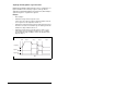
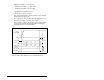
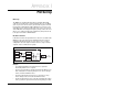
• Digital In1 Sel (A051) = 4 “Preset Freq”
– Digital In2 Sel (A052) = 18 “Timer Start”
– Relay Out Sel (A055) = 16 “Timer Out”
– Relay Out Level (A056) = 20.0 Sec
– Preset Freq 1 (A071) = 30.0 Hz
• The control terminal block is wired such that a start command
will also trigger the timer start.
• The relay output is wired to I/O Terminal 05 (Digital Input 1) so
that it forces the input on when the timer starts.
• After the timer is complete, the output is turned off releasing the
preset speed command. The drive defaults to following the
analog input reference as programmed.
Note that a “Reset Timer” input is not required for this example
since the “Timer Start” input both clears and starts the timer.
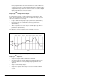
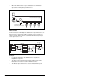
Di
g
ital In
2
Reset
C
ounte
r
Limit
S
witc
h
Di
g
ital In
1
C
ounter I
n
Photo E
ye
S
tar
t
Out
p
u
t
Frequenc
y
Rela
y
Ou
t