
Owner manual
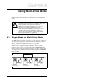
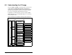


Using Multi-Drive Mode 8-7
Important: MDCOMM-PBUS parameters can be set using MDI
peripheral (OIM, V*S Utilities with MDCOMM-232,
etc.) ONLY when the Mode Jumper is in Single mode
position.
8.5 Multi- Mode Explicit Messaging
Parameter addressing for Explicit messaging in Multi-Drive is similar
to that in Single mode.
The parameter numbers range from 1 to 2047. Parameter numbers
1-1023 are used to access the drive or module parameters.
Parameter numbers 1024-2047 are used to access the Module
Fault Codes, Events and Diagnostic Items.
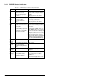
For example, to access Accel Time (parameter 39) for Drive 0, Drive
0-1 to Drive 0-4 in Multi-Drive mode:
8.6 Additional Information
• When the MD65 with the MDCOMM-PBUS module (Drive 0) is
powered up, all configured daisy-chained drives must be present
before an I/O connection is allowed on Profibus (i.e. before the
drives can be controlled).
• If the MD65 with the MDCOMM-PBUS module (Drive 0) is
powered down, communications with the four daisy-chained
drives (Drives 0-1 to Drives 0-4) are disrupted and the drives will
fault.
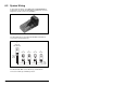
• If any of the daisy-chained drives (Drive 0-1 to Drive 0-4) are
powered down, the respective Input Image (Logic Status and
Feedback) sent to the scanner will be zeros, and the NET A and
DRIVE LEDs on the MDCOMM-PBUS module will flash red.
Status information from the scanner will not indicate there is a
fault at the node.
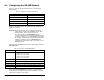
Table 8.3 – Accessing Accel Time (Parameter 39)
Module
IND
(0-2 bits)
Parameter
Number
Drive 0 Single Drive 000 39
Drives 0-1 Multi Drive 001 39
Drives 0-2 Multi Drive 010 39
Drives 0-3 Multi Drive 011 39
Drives 0-4 Multi Drive 100 39