
Owner manual


8-6 PROFIBUS Communications Module
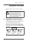
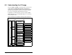
8.4 Configuring the RS-485 Network
Table 8.1 shows the parameters that must be set in the daisy-
chained drives.
Note: The RS-485 network is fixed at 19.2K baud, 8 data bits, no
parity, and 1 stop bit.
Important:Parameter A105 (Comm Loss Action) in the daisy-
chained drives is still used in Multi-Drive mode. If the
RS-485 cable is disconnected or broken, the
disconnected drive(s) will immediately take the
corresponding Comm Loss Action(s). Parameter A106
(Comm Loss Time) is not used in Multi-Drive mode. On
the Profibus, Comm Flt Action (parameter 09) and Idle
Flt Action (parameter 10) in the MDCOMM-PBUS
determine the action taken for ALL of the drives on the
Multi-Drive node.
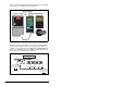
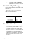
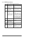
Table 8.2 shows the Multi-Drive parameters that must be set in the
MDCOMM-PBUS.
After setting the MDCOMM-PBUS parameters, set the Module
Mode Jumper from Single drive operation to Multi-Drive operation,
and reset the module or cycle power.
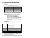
Table 8.1 – Parameters for daisy-chained drives
Parameter Value
P36 (Start Source) 5 (RS485 (MDI) Port)
P38 (Speed Reference) 5 (RS485 (MDI) Port)
A103 (Comm Data Rate) 4 (“19.2K”)
A104 (Comm Node Addr) 1-247 (must be unique)
A107 (Comm Format) 0 (“RTU 8-N-1”)
Table 8.2 – Parameters for MDCOMM-PBUS
Parameter Value
11 (MDI I/O Cfg) 0 = Drive 0 connected
1 = Drives 0-1 connected
2 = Drives 0-2 connected
3 = Drives 0-3 connected
4 = Drives 0-4 connected
17 (Drv 0 Addr) = Parameter A104 (Comm Node Address) in Drive 0
18 (Drv 1 Addr) = Parameter A104 (Comm Node Address) in Drive 0-1
19 (Drv 2 Addr) = Parameter A104 (Comm Node Address) in Drive 0-2
20 (Drv 3 Addr) = Parameter A104 (Comm Node Address) in Drive 0-3
21 (Drv 4 Addr) = Parameter A104 (Comm Node Address) in Drive 0-4