
Owner manual


Configuring the PROFIBUS Scanner 5-13
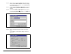
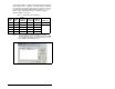
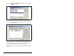
scanner, “Configured Program” will be displayed in the
message window (see figure 5.20).
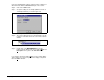
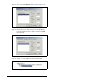
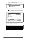
Step 20. Click F
ile and Save As from the tool bar, as a unique File
N
ame. The configuration of the scanner is now complete.
Note that cycling power to the scanner is recommended.
See figure 5.21.
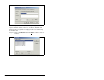
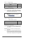
Summary of the example scanner configuration:
Figure 5.20 – Network Window Scanner Selection
Figure 5.21 – Save As Dialog Window
Module
M0 / M1 Addressing
Station 1 Station 2
Logic Command / Status 0 6
Reference / Feedback 1 7
Parameter Access 2 8