
Owner manual


Configuring the PROFIBUS Scanner 5-9
In our example, Station 1 will be controlled using Logic Command /
Status and Reference / Feedback. The Parameter Access will also
be used. Because the Mode Jumper J2 on the module is set to “1X”
for Single Drive (default) and MDI I/O Cfg (parameter 11) is set to
Drive 0. Logic Command/Reference uses 4 bytes and Logic
Status/Feedback uses 4 bytes.
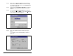
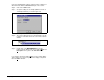
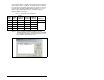
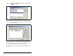
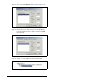
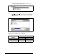
Step 11. Select “Ctrl/Stat & Ref/Fdbk (2+2bytes)” from the
“Available Modules” list as shown in figure 5.13. Click OK.
The “Ctrl/Stat & Ref/Fdbk” (2+2 bytes) module has now
been added as shown in figure 5.13.
Table 5.1 – Input/Output Size Configurations
Input
Size
Output
Size
Logic
Command/
Feedback
Reference/
Feedback
MDI I/O
Cfg (11) Mode (1)
44
✔✔Drive 0 Single
88
✔✔Drives 0-1 Multi-Drive
12 12
✔✔Drives 0-2
16 16
✔✔Drives 0-3
20 20
✔✔Drives 0-4
Figure 5.13 – Modules: Ctrl/Stat & Ref/Fdbk Viewing Window