
Owner manual


3-2 PROFIBUS Communications Module
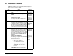
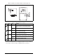
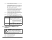
Switches
1
1. The factory default states of all switches are UP, and have the default
address of 3.
Description
SW1 Least Significant Bit (LSB) of Node Address
SW 2 Bit 1 of Node Address
SW 3 Bit 2 of Node Address
SW 4 Bit 3 of Node Address
SW 5 Bit 4 of Node Address
SW 6 Bit 5 of Node Address
SW 7 Most Significant Bit (MSB) of Node Address
SW 8 SW8 Firmware Update
Figure 3.1 – Setting the Node Address
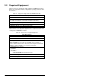
Table 3.1 – SW8 Setting
SW 8 Setting Description
0 Write Access Firmware Update
1 Normal Operating State
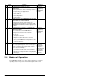
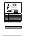
J2
J2
Single Drive
Operation
Multi-Drive
Operation
2
1
8
3
4
5
6
7
NODE
ADDRESS SWITCHES
UP = OPEN = 1
2
1
8
3
4
5
6
7
J3
SWAP
J4
J1