
Owner manual


Getting Started 2-1
CHAPTER 2
Getting Started
This chapter provides:
• A description of the PROFIBUS module components
• A list of parts shipped with the module and a list of user-supplied
parts required for installing the module
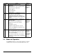
• An installation checklist
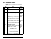
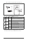
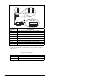
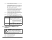
2.1 PROFIBUS Module Components
Status Indicators Three LEDs to indicate the status of the
connected drive, module, and network.
MDI Connector A 20-pin, single-row shrouded male header. An
Internal Interface cable connects to this
connector and a connector on the drive.
PROFIBUS
Connector
A 9-pin, female D-Sub connector.
Node Address
Switches/ Firmware
Update Switches
Switches (SW1-7) for setting the node address
and SW8 for Firmware flash updating.
Mode Jumper (J2) Selects Single or Multi-Drive mode of
operation.
SWAP Jumper (J3) Determines the Intel or Motorola (SWAP) data
format for the corresponding PLC.
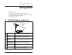
Figure 2.1 – Components of the PROFIBUS Module
➊
➋
➌
➍
➎
❻