MD65 PROFIBUS Communications Module M/N MDCOMM-PBUS Instruction Manual D2-3530
The information in this manual is subject to change without notice. Throughout this manual, the following notes are used to alert you to safety considerations: ! ATTENTION: Identifies information about practices or circumstances that can lead to personal injury or death, property damage, or economic loss. Important: Identifies information that is critical for successful application and understanding of the product. ! ATTENTION: The drive may contain high voltages that can cause injury or death.
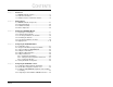
CONTENTS Chapter 1 Introduction 1.1 PROFIBUS Module Features ........................................ 1-1 1.2 Related Documentation ................................................. 1-2 1.3 Getting Assistance from Reliance Electric..................... 1-2 Chapter 2 Getting Started 2.1 PROFIBUS Module Components .................................. 2-1 2.2 Required Equipment ...................................................... 2-2 2.3 Installation Checklist ...............................................
Chapter 6 About I/O Messaging 6.1 About I/O Messaging ..................................................... 6-1 6.2 Understanding the I/O Image......................................... 6-1 6.3 Using Logic Command/Status ....................................... 6-2 6.4 Using Reference/Feedback ........................................... 6-3 Chapter 7 Using Explicit Messaging (Parameter Protocol) 7.1 About Explicit Messaging............................................... 7-1 7.2 Running Explicit Messages...
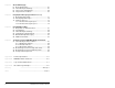
List of Figures Figure 2.1 – Components of the PROFIBUS Module ................................. 2-1 Figure 2.2 – Status Indicators ..................................................................... 2-5 Figure 3.1 – Setting the Node Address....................................................... 3-2 Figure 3.2 – ERNI and Phoenix Subcon Connectors.................................. 3-5 Figure 3.3 – Network Wiring Diagram......................................................... 3-5 Figure 3.
Figure 8.1 – Single Mode Example for Network.......................................... 8-1 Figure 8.2 – MDI Peripheral Devices for Single Mode Connection............. 8-2 Figure 8.3 – Multi-Drive Mode Example for Network .................................. 8-2 Figure 8.4 – AK-U0-RJ45-TB2P Terminal Block Connector ....................... 8-4 Figure 8.5 – Multi-Drive Mode Example for Network .................................. 8-4 Figure 8.6 – Multi-Drive Mode Example of I/O Image ..............................
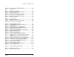
List of Tables Table 2.1 – Equipment Shipped with the PROFIBUS Module .................... 2-2 Table 2.2 – Required User-Supplied Equipment ........................................ 2-2 Table 2.3 – Status Indicator Descriptions ................................................... 2-5 Table 3.1 – SW8 Setting ............................................................................. 3-2 Table 3.2 – Node Address Switch Settings (UP = OPEN = 1).................... 3-3 Table 3.3 – Jumper Settings ..............
VI PROFIBUS Communications Module
CHAPTER 1 Introduction This manual provides information about the PROFIBUS Communications module (MDCOMM-PBUS) and using it with MD65 drives. It is intended for qualified electrical personnel familiar with installing, programming, and maintaining AC drives and networks. The PROFIBUS module is an embedded communication option for MDI AC drives, such as the MD65 drive. The module is mounted in the drive and receives its required power from the drive.
1.2 • User-defined fault actions determine how the module and MD65 drive respond to communication disruptions (faults) on the network and controllers in idle mode. • For Single Drive mode, the slave device’s parameters on the Profibus network can be configured and monitored by the software tool V*S Utilities. Related Documentation Refer to the following related publications as necessary for more information. All of the publications are available from http://www.theautomationbookstore.com or http://www.
CHAPTER 2 Getting Started This chapter provides: 2.1 • • A description of the PROFIBUS module components • An installation checklist A list of parts shipped with the module and a list of user-supplied parts required for installing the module PROFIBUS Module Components ➊ ➎ ➋ ❻ ➍ ➌ Status Indicators Three LEDs to indicate the status of the connected drive, module, and network. MDI Connector A 20-pin, single-row shrouded male header.
2.2 Required Equipment Table 2.1 lists the equipment shipped with the PROFIBUS module. When you unpack the module, verify that the package includes all of these items. Table 2.1 – Equipment Shipped with the PROFIBUS Module Item Description One MDCOMM-PBUS PROFIBUS module A 2.54 cm (1 in) and a 12.7 cm (5 in) Internal Interface cable (only one cable is needed to connect the module to the drive) One grounding wrist strap One floppy disc with GSD file PROFIBUS Module User Manual (D2-3530) Table 2.
2.3 Installation Checklist This section is designed to help experienced users start using the PROFIBUS module. If you are unsure about how to complete a step, refer to the referenced chapter. 4 Step ❒ 1 Review the safety precautions for the module. Throughout this manual ❒ 2 Verify that the MD65 drive is properly installed. MD65 AC Drive User Manual (D2-3519) ❒ 3 Commission the module.
4 Step ❒ 7 Action Refer to: Configure the module for your application. Set the parameters for the following features as required by your application: • • • ❒ 8 Chapter 4, Configuring the PROFIBUS Module Node address I/O configuration Fault actions Apply power to the PROFIBUS master and other devices on the network. Verify that the master and network are installed and functioning in accordance with PROFIBUS standards, and then apply power to them.
Table 2.3 describes the status indicators shown in figure 2.2. ➊ ➋ ➌ DRIVE MS NET A NET B ➊ ➋ ➌ ➍ Figure 2.2 – Status Indicators Item Status Indicator Table 2.3 – Status Indicator Descriptions Status1 Description DRIVE Green MS Flashing Green Green NET A Flashing Green Green NET B Flashing Green Off Normal Operation. The module is properly connected and is communicating with the drive. Not used. Normal Operation. The module is operational and is transferring I/O data. Normal Operation.
2-6 PROFIBUS Communications Module
CHAPTER 3 Installing the PROFIBUS Module Chapter 3 provides instructions for installing the PROFIBUS module in a MD65 drive. 3.1 Preparing for an Installation Before installing the PROFIBUS module, verify that you have all required equipment. Refer to chapter 2, Getting Started. 3.2 Commissioning the Module To commission the module, you must set a unique node address and check the data rate that is used by the network and set in the GSD-file.
J3 J2 J2 SWAP Single Drive Operation Multi-Drive Operation NODE ADDRESS SWITCHES J4 1 2 3 4 5 6 7 8 J1 1 2 3 4 5 6 7 8 UP = OPEN = 1 Switches1 Description SW1 Least Significant Bit (LSB) of Node Address SW 2 Bit 1 of Node Address SW 3 Bit 2 of Node Address SW 4 Bit 3 of Node Address SW 5 Bit 4 of Node Address SW 6 Bit 5 of Node Address SW 7 Most Significant Bit (MSB) of Node Address SW 8 SW8 Firmware Update Figure 3.1 – Setting the Node Address 1.
Table 3.
Step 2. Verify the Network Baud rate, which is set by the network master and depends on cable length. The MDCOMM-PBUS module uses the Auto-Baud and supports the following different data rates: 9.6 kpbs, 19.2 kpbs, 45.45 kpbs, 93.75 kpbs, 187.5kpbs, 500 kpbs, 1.5 Mpbs, 3 Mpbs, 6 Mpbs, and 12 Mpbs. The Auto-Baud function allows the module to recognize the current baud rate and sets itself to the transmission rate by the master automatically.
Step 4. Connect a PROFIBUS connector to the cable. Only use cable that conforms to Profibus cable standards. Belden #3079A Profibus cable or equivalent is recommended. Note: PROFIBUS connectors are available from a variety of sources and in various sizes. As such, there may be mechanical limitations that prohibit the use of some connectors.
Table 3.4 – MDCOMM-PBUS DB-9 Pin Layout (Continued) Terminal 4 5 6 7 8 Signal RTS GND BUS +5V BUS Not connected A-LINE 9 Not connected Step 5. Function Isolated GND from bus Isolated +5V from bus Negative RxD/TxD according to RS485 specification Connect the PROFIBUS cable to the module, secure it with the two screws on the connector, and route it through the bottom of the MD65 drive. See figure 3.3. Note: The screws on some connectors tie the PROFIBUS cable ground/shield to the metal of the socket.
To meet the requirements of EN55011 Class A or B, the conditions listed below must be satisfied. Switching Frequency of MD65 EN55011 Class A EN55011 Class B 4 kHz Use one ferrite Ferrishield (part No. HI28B2039) or Fair-Rite (part No. 0443164151) 6 kHz No ferrite required 8 kHz 16 kHz Use three clip ferrites TDK, type ZCAT 3035-1330 Note: For the conditions to satisfy the essential requirements for CE compliance on MD65 drives. please refer to the MD65 manual, D2-3519.
3.5 Connecting the Module to the Drive Step 1. Remove power from the drive. Step 2. Use static control precautions. Step 3. Mount the module on the required special drive cover (ordered separately). • C Frame: Use the module screw to secure the module to the cover. • B Frame: Disregard the screw and snap the module in place. Important:For C Frame drives, tighten the module’s lower left screw to ground the module.
Profibus Module ➊ ➋ ➍ MD65 Drive B and C Frames (cover removed) ➌ Back of Cover Back of Required Special Drive Cover (ordered separately): Part Number 6MD-COMMCVRB for B Frame Part Number 6MD-COMMCVRC for C Frame MDI Connector 15.24 cm (6 in) Internal Interface cable PROFIBUS cable Retaining screws Figure 3.
Module Mounted on Back of Cover MD65 Drive B and C Frames (cover removed) Ground for C Frame Drives For B Frame drives, the lower left module screw does not ground the module. To ground the module, install the special drive cover onto the drive using both cover fasteners. Figure 3.7 – Mounting the Adapter 3.6 Applying Power ! 3-10 ATTENTION: Unpredictable operation may occur if parameter settings and switch settings are not compatible with your application.
Step 3. Apply power to the drive. The module receives its power from the connected drive and the network. When you apply power to the product and network for the first time, the status indicators should be green after an initialization. If the status indicators are red, there is a problem. Refer to chapter 8, Troubleshooting the PROFIBUS Module and Network. Step 4. Apply power to the master device and other devices on the network.
Installing the PROFIBUS Module 3-12
CHAPTER 4 Configuring the PROFIBUS Module Chapter 4 provides instructions and information for setting the parameters in the module. For a complete list of parameters, refer to Appendix B, PROFIBUS Module Parameters. For definitions of terms in this chapter, refer to the Glossary. 4.1 Configuration Tools The PROFIBUS module stores parameters and other information in its own non-volatile memory. Therefore, you must access the module to view and edit its parameters. Table 4.
4.2 Using the LCD OIM to Configure the Module Use the procedure in figure 4.1 to access the parameters on the PROFIBUS module using the LCD OIM. If you are unfamiliar with the operation of the LCD OIM, refer to the MD65 AC Drive User Manual (D2-3519) for more information. Table 4.2 – Using the LCD OIM or CopyCat Keypad Step Key(s) 1. Power up the drive. Plug the OIM or CopyCat Keypad into the drive. The Parameters menu for the drive will be displayed. 2.
Table 4.2 – Using the LCD OIM or CopyCat Keypad Step Key(s) 4. Press Enter to select the Profibus module. The Parameters menu for the module will be displayed. Example Screens Parameters Linear List Changed Params DIAG 5. Press Enter to access the parameters. Edit the module parameters using the same techniques that you use to edit parameters. 4.
4.4 Setting the Node Address The PROFIBUS Node address/Firmware Update State is set through the use of an 8-bit DIP switch. The low seven bits let you set a node address and the valid address allows binary coding 1 through 125. New settings of node address are recognized only when power is applied to the module, cycle power, or a Reset Module Command. The MSB bit provides write access for the module flash firmware update. In normal operating state, SW8 should be set to 1.
4.5 Setting the I/O Configuration The I/O configuration determines the number of drives that will be represented on the network as one node by the module. If the Mode Jumper is set to the Single mode position, only one drive is represented by the module and MDI I/O Cfg (parameter 11) has no effect. If the Mode Jumper J2 is set to the Multi-Drive position, up to five drives can be represented as one node by the module. Step 1.
4.6 Setting a Fault Action ATTENTION: Comm Flt Action (parameter 9) and Idle Flt Action (parameter 10) let you determine the action of the module and connected drive if communications are disrupted or the scanner is idle. By default, these parameters fault the drive. You can set these parameters so that the drive continues to run. Precautions should be taken to ensure that the settings of these parameters do not create a risk of injury or equipment damage.
Changes to these parameters take effect immediately. A reset is not required. If Multi-Drive mode is used, the same fault action is used by the module for all of the drives it controls (Drive 0, Drives 0-1 to Drives 0-4). 4.6.2 Setting the Fault Configuration Parameters If you set module Comm Flt Action (parameter 9) or module Idle Flt Action (parameter 10) to “Send Flt Cfg,” the values in the parameters shown in table 4.4 are sent to the drive after a communications fault and/or idle fault occurs.
Set parameter 8 (Reset Module) to “Reset Module.” See figure 4.4. Reset Module Parameter: # Ready VALUE LIMITS 008 0 Value 0 1 2 Description Ready (Default) Reset Module Set Defaults SEL X Figure 4.4 – Reset Screen on an LCD OIM When you enter 1 (“Reset Module”), the module will be immediately reset. When you enter 2 (“Set Defaults”), the module will set all module parameters to their factory-default settings. The value of this parameter will be restored to 0 (“Ready”) after the module is reset.
CHAPTER 5 Configuring the PROFIBUS Scanner PROFIBUS scanners are available from several manufacturers, including SST. SST PROFIBUS scanners come with a software tool for configuring the scanner (see figure 5.2). Chapter 5 provides instructions on how to utilize the SST PROFIBUS configuration software tool to: • • Install the MDCOMM-PBUS GSD file in the software tool library. Configure the SST-PFB-SLC PROFIBUS scanner.
COMM LED SYS LED Config Port Front Label Station 0 PROFIBUS Port MD65 Station 1 MD65 Station 2 Figure 5.1 – Example PROFIBUS Network 5.2 SST Profibus Configuration Software Tool SST Profibus Scanners come with a software tool for configuring the scanner. See figure 5.2. Device Library window Network Configuration window Online Browse window Figure 5.
5.3 Installing the MDCOMM-PBUS GSD File in the Software Tool Library GSD files are used by software tools to configure the network, in other words, to map and define the I/O in a PROFIBUS scanner. A GSD file is required for each type of module on the network. For example: The MDCOMM-PBUS GSD file is “R_E_07FF.gsd” and a copy of the file is provided on a floppy disk with each MDCOMM-PBUS PROFIBUS module. The file can also be downloaded from the Internet by going to: www.reliance.com.
Figure 5.4 – Add PROFIBUS Devices Applet Window Step 3. Find the directory location of the data file(s) you wish to add (typically, the source location is a floppy disk in drive A:). “R_E_07FF.gsd” is the GSD file for the MDCOMM-PBUS as shown in figure 5.5. Figure 5.5 – Adding the GSD File for the RECOMM-PBUS Step 4. 5-4 Select “R_E_077FF.gsd” for the MDCOMM-PBUS and click Open.
Step 5. Click on the (+) sign of the Slaves folder as shown in figure 5.6. Figure 5.6 – Masters/Slaves Library Window The software tool will automatically create a Reliance Electric sub-folder (in the Slaves folder) if it does not already exist. The MDCOMM-PBUS is now shown in the library and the software tool is now ready to configure a MDCOMM-PBUS on a PROFIBUS network. 5.
Step 2. Click on the (+) sign of the Slaves folder in the Library window and the Reliance Electric sub-folder to display the available Profibus DP slaves or the RECOMM-PBUS slave. Refer to figure 5.6. Step 3. Double-click the SST-PFB-SLC MASTER in the Masters folder in the Library window to add the scanner to the network. Step 4. A user-defined Name and Description can be given to the scanner. In our example, the scanner will be Station 0 on the network, as shown in figure 5.7. Figure 5.
Connection and Baud Rate settings configure how the software tool will communicate with the CONFIG RS232 port on the scanner. Step 6. Click on the COM Port tab. Step 7. Accept the settings in our example (COM1 on the PC at 115200 bps baud rate), as shown in figure 5.9. Figure 5.9 – COM Port Default Settings Step 8. The scanner will appear in the network window as shown in figure 5.10. Double-click on the scanner in the network window. Figure 5.10 – Scanner Network Window Step 9.
Figure 5.11 – Reliance Electric Library Dialog Window Logic Command / Status, Reference / Feedback, Datalinks and Parameter Access (explicit messaging) modules are added using the Modules tab. Step 10. Click on the Modules tab. Click Add to view the choice of modules. Figure 5.
In our example, Station 1 will be controlled using Logic Command / Status and Reference / Feedback. The Parameter Access will also be used. Because the Mode Jumper J2 on the module is set to “1X” for Single Drive (default) and MDI I/O Cfg (parameter 11) is set to Drive 0. Logic Command/Reference uses 4 bytes and Logic Status/Feedback uses 4 bytes. Table 5.
Step 12. Click Add to continue adding modules. Select “Parameter Access” and click OK. Figure 5.14 – Add Modules: Parameter Access Selection Window Step 13. The “Parameter Access” module has now been added as shown in figure 5.15. Figure 5.15 – Modules: Parameter Access Viewing Window Settings can be chosen to map Station models to SLC addresses. In our example M1/Mo files are used for Input / Output. Note that the Reference/Feedback (Ctrl/Stat & Ref/Fdbk) start at word 0.
Step 14. Click on the SLC Address tab as shown in figure 5.16. Figure 5.16 – SLC Address: M1/M0 (Ctrl/Stat & Ref/Fdbk) Step 15. Parameter Access starts at word 10 in the M1/M0 files. Note that Parameter Access utilizes 4 words. Click OK when finished. Figure 5.17 – SLC Address: M1/M0 (Parameter Access) Step 16. Station 1 is now displayed in the network window. Figure 5.
Station 1 is configured as follows: Table 5.2 – Station 1 Configurations Module M1/M0 Word Ctrl/Stat & Ref Fdbk Drive 0 0 Parameter Access 2 Note that Station 1 occupies 6 words. Step 17. The same steps for configuring Station 1 will be used to configure Station 2. Refer to previous steps (beginning with step 9) for Configuring the SST-PFB-SLC PROFIBUS Scanner Station 2. Refer to figure 5.19. Figure 5.19 – Station 2 Network Window Station 2 is configured as follows: Table 5.
scanner, “Configured Program” will be displayed in the message window (see figure 5.20). Figure 5.20 – Network Window Scanner Selection Step 20. Click File and Save As from the tool bar, as a unique File Name. The configuration of the scanner is now complete. Note that cycling power to the scanner is recommended. See figure 5.21. Figure 5.
5-14 PROFIBUS Communications Module
CHAPTER 6 Using I/O Messaging Chapter 6 provides information and examples that explain how to use I/O Messaging to control an MD65 drive. ! 6.1 ATTENTION: The examples in this publication are intended solely for purposes of example. There are many variables and requirements with any application. Rockwell Automation does not assume responsibility or liability (to include intellectual property liability) for actual use of the examples shown in this publication.
The I/O image table will vary based on the configuration of the Mode Jumper (J2) on the module and MDI I/O Cfg (parameter 11). The image table always uses consecutive words starting at word 0. Figure Figure 6.1 illustrates an example of a drive I/O image (16-bit words).
6.4 Using Reference/Feedback When enabled, Reference/Feedback always begins at word 1 in the I/O image. The Reference (16 bits) is produced by the controller and consumed by the module. The Feedback (16 bits) is produced by the module and consumed by the controller. Size 16-bit 1 Valid Values1 0.0 to 4000 0.0 to 240.0 Hz (MD60) or 0.0 to 400.0 Hz (MD65) In I/O Image Example Word 1 Figure 6.1 The Reference for a MD65 or MD60 is set in Hz. For example, “300” equates to 30.
6-4 PROFIBUS Communications Module
CHAPTER 7 Using Explicit Messaging (Parameter Protocol) Chapter 7 provides information and examples that explain how to use Explicit Messaging to monitor and configure the module and connected MD65 drive, as well as other peripherals. ! ATTENTION: The examples in this publication are intended solely for purposes of example. There are many variables and requirements with any application.
Refer to step 21 in chapter 5 to view the procedure for adding the “Parameter Access” module to a configuration. This maps four words input and output to the end of the I/O configuration, which is used as the request/response in the parameter message format (figure 7.2). 7.2 Running Explicit Messages There are five basic events in the Explicit Messaging process defined in figure 7.1. The details of each step will vary depending on the controller. Refer to the documentation for your controller.
7.3 Parameter Protocol This protocol uses four words in the PROFIBUS I/O area. Requests and responses are a handshake procedure and cannot be batched, meaning that if the master sends a request, it has to wait for the response before sending a new request.
7.3.1 Parameter Message Request Table 7.1 – Parameter Message Request Data Word 1 Description PNU - Parameter Number (Bit 0-10) The parameter number determines which parameter to access in the selected peripheral. Parameters 1-1023 can be accessed. Parameter numbers 1024 - 2047 are used to access the fault object. Parameter 1024 is equal to the latest fault, 1025 to the prior fault, and so on.
Table 7.1 – Parameter Message Request Data Word 2 Description IND - Index The IND is used to specify which drive will receive a message. 0-2 bits = MDI port Bit Definitions 000 Drive 0 single drive mode 001 Drives 0-1 multi-drive mode 010 Drives 0-2 multi-drive mode 011 Drives 0-3 multi-drive mode 101 Drives 0-4 multi-drive mode 3 - 15 = Reserved 3 PVA - Parameter value Spare 4 PVA - Parameter value (8-bit & 16-bit word).
Table 7.2 – Parameter Message Response Data Word 2 IND - Index Description 3 Port ID of requested parameter PVA - Parameter value 4 Spare PVA - Parameter value (8-bit & 16-bit word). Read Response: Contents the value from a 8-bit or 16-bit parameter or the Fault Code (if RC = 7). Write Response: Confirms the write value for a 8-bit or 16bit parameter or the Fault Code (if RC = 7). Table 7.
CHAPTER 8 Using Multi-Drive Mode Chapter 8 provides information to explain how to use Multi-Drive mode. ATTENTION: The examples in this publication are intended solely for purposes of example. There are many variables and requirements with any application. Rockwell Automation, Inc. does not assume responsibility or liability (to include intellectual property liability) for actual use of the examples shown in this publication.
Figure 8.2 shows that the Single Drive mode provides the possibility of connecting one additional external peripheral. MDI LANG LANG DISP PROG DISP Prog 7 8 9 4 5 6 1 2 3 . 0 +/- DEL ALT ALT Esc JOG JOG Figure 8.2 – MDI Peripheral Devices for Single Mode Connection Multi-Drive mode is an alternative to the typical network installation, where a single Profibus node can consist of one to five drives (see figure 8.3). The first drive must be a MD65 with a MDCOMM-PBUS module.
The multiple drive connectivity, up to five drives with at least one MD65 drive, for example, one MD65 and four MD60 drives, provides a low cost Profibus solution in the industry for multiple drives. Important: In Multi-Drive mode, the unit will not operate with MDI peripheral devices such as the OIM or the MDCOMM232 and the application of any other peripheral will be prohibited. Benefits of Multi-Drive mode include: • Lower hardware costs. Only one MDCOMM-PBUS module is needed for up to five drives.
8.2 System Wiring To daisy-chain the drives of the MD65 with the MDCOMM-PBUS module (Drive 0), the AK-U0-RJ45-TB2P terminal block connector (Figure 8.4) can be used for easy installation. Figure 8.4 – AK-U0-RJ45-TB2P Terminal Block Connector The wiring diagram for using AK-U0-RJ45-TB2P terminal block connectors is shown in figure 8.5. To MD65 with MDCOMM-PBUS To Drive #2 To Drive #3 To Drive #4 To Drive #5 120 Ω ¼ Watt Resistor 120 Ω ¼ Watt Resistor Figure 8.
8.3 Understanding the I/O Image The terms input and output are defined from the scanner’s point of view. Therefore, Output I/O is data that is output from the scanner and consumed by the Profibus module. Input I/O is status data that is produced by the module and consumed as input by the scanner. The I/O image table will vary based on the: Configuration of the Mode Jumper (J2) on the module and MDI I/O Cfg (parameter 11). The image table always uses consecutive words starting at word 0. Figure 8.
8.4 Configuring the RS-485 Network Table 8.1 shows the parameters that must be set in the daisychained drives. Table 8.1 – Parameters for daisy-chained drives Parameter Value P36 (Start Source) 5 (RS485 (MDI) Port) P38 (Speed Reference) 5 (RS485 (MDI) Port) A103 (Comm Data Rate) 4 (“19.2K”) A104 (Comm Node Addr) 1-247 (must be unique) A107 (Comm Format) 0 (“RTU 8-N-1”) Note: The RS-485 network is fixed at 19.2K baud, 8 data bits, no parity, and 1 stop bit.
Important: 8.5 MDCOMM-PBUS parameters can be set using MDI peripheral (OIM, V*S Utilities with MDCOMM-232, etc.) ONLY when the Mode Jumper is in Single mode position. Multi- Mode Explicit Messaging Parameter addressing for Explicit messaging in Multi-Drive is similar to that in Single mode. The parameter numbers range from 1 to 2047. Parameter numbers 1-1023 are used to access the drive or module parameters.
8-8 PROFIBUS Communications Module
CHAPTER 9 Troubleshooting the PROFIBUS Module and Network Chapter 9 contains information for troubleshooting the PROFIBUS module and the network. 9.1 Understanding the Status Indicators The PROFIBUS module has three status indicators. They can be viewed on the module or through the drive cover. (See figure 9.1.) ➊ ➋ ➌ ➊ ➋ ➌ ➍ DRIVE MS NET A NET B Number Status Indicator Description Refer to... DRIVE MDI Connection Status Section 9.1.1 MS Module Status Section 9.1.
9.1.1 DRIVE Status Indicator Table 9.1 – DRIVE Status Indicator: State Definitions Status Off Cause The module is not powered or is not connected properly to the drive. Flashing The module is not Red receiving a ping message from the drive. Solid Red Corrective Action • Securely connect the module to the drive using the ribbon cable. • • Apply power to the drive. • Cycle power to the drive. Verify that cables are securely connected.
9.1.2 MS Status Indicator Table 9.2 – MS Status Indicator: State Definitions Status Off Cause The module is not powered. Flashing The module has Red faults or a drive is missing in MultiDrive mode. Solid Red The module has failed the hardware test. Flashing The module is Green operational but is not transferring I/O data. Solid Green The module is operational and transferring I/O data. Corrective Action • Securely connect the module to the MD65 drive using the ribbon cable.
9.1.3 NET A Status Indicator Table 9.3 – NET A Status Indicator: State Definitions Status Off Cause The module is not powered or is not connected properly to the network or the Node Address is wrong. Flashing Error in PROFIBUS Red configuration. Solid Red Corrective Actions • Securely connect the module to the drive using the Internal Interface cable and to the network using a PROFIBUS cable. (Screw D-shell to the module.) • Check the SW8 of DIPSwitches and set it to one Normal operating state.
9.2 Module Diagnostic Items in Single Drive Mode Table 9.4 lists diagnostic items that can be accessed using V*S Utilities software or the LCD OIM. Table 9.4 – Module Diagnostic Items for Single Drive Mode No. Event Description 1 Field Flash Cnt The number of Firmware Updates. 2 Module Events The number of events in the event queue. 3 Reference Reference from PROFIBUS returned to MDI drive. 4 Logic Cmd Command from PROFIBUS returned to MDI drive.
Table 9.5 – Module Diagnostic Items (Continued)for Multi-Drive Mode No. Event Description 10 Drv 1 Feedback Feedback from Drives0-1 returned to Profibus 11 Drv 2 Reference Reference from Profibus returned to MDI Drives 0-2. 12 Drv 2 Logic Cmd Command from Profibus returned to MDI Drives 0-2. 13 Drv 2 Logic Sts Status of the Drives 0-2 returned to Profibus. 14 Drv 2 Feedback Feedback from Drives 0-2 returned to Profibus 15 Drv 3 Reference Reference from Profibus returned to MDI Drives 0-3.
9.4 Viewing and Clearing Events The module maintains an event queue that reports the history of its actions. You can view the event queue using an LCD OIM or VS Utilities software. Figure 9.2 – Viewing and Clearing Events Using an LCD OIM Events Many events in the event queue occur under normal operation. If you encounter unexpected communications problems, the events may help you or Reliance Electric personnel troubleshoot the problem. Table 9.6 lists events that may appear in the event queue. Table 9.
Table 9.6 – Event Codes and Descriptions Code Event Description 11 MDI Bus Off Flt A bus-off condition was detected on MDI. This event may be caused by loose or broken cables or by noise. 13 P-DP Idle The PROFIBUS Module received a Network Clear from the PROFIBUS Master. 14 P-DP Online The PROFIBUS Module has gone on-line the PROFIBUS network. 15 P-DP Offline The PROFIBUS Module has gone off-line the PROFIBUS network. 17 MDI Fault Msg The Host Faulted.
APPENDIX A Technical Specifications Communications Network Protocol Data Rates Drive Protocol PROFIBUS 9.6 kpbs, 19.2 kpbs, 93.75 kpbs, 187.5 kpbs, 500 kpbs, 1.5 Mbps, 3 Mbps, 6 Mbps, 12 Mbps. The module has auto baud rate detection. MDI Electrical Drive Network 370 mA at 5 V supplied through the drive. Mechanical Dimensions Height Length Width 19 mm (0.75 in) 86 mm (3.39 in) 78.5 mm (3.
Environmental Temperature Operating Storage -10 to +50°C (14 to 149°F) -40 to +85°C (-40 to 185°F) Relative Humidity -5 to 95% non-condensing Vibration 1.0 G Operational 2.5 G Non-operational Shock 15.0 G Operational 30.0 G Non-operational Altitude 1,000m (3,300 ft.
APPENDIX B PROFIBUS Module Parameters The following information is provided for each PROFIBUS module parameter along with its description: Parameter Number: Unique number assigned to each parameter. Parameter Name: Unique name assigned to each parameter. Range: Predefined parameter limits or selections. Default: Factory default setting. Type: Read Only or Read/Write Reset Required: Module must be reset before parameter value is recognized.
1 Mode Range: 0 = Single Drive 1 = Multiple Drive Default: N/A Type: Read Only Reset Required: N/A Displays the Single or Multi-Drive operating mode selected with the jumper J2 on the module. 4 P-DP Addr Actual Range: 0 to 125 Default: N/A Type: Read Only Reset Required: N/A Displays the PROFIBUS node address actually used by the module. 5 P-DP Rate Actual Range: 0 = 9.6 kpbs 1 = 19.2 kpbs 2 = 45.45 kpbs 3 = 93.75 kpbs 4 = 187.5 kpbs 5 = 500 kpbs 6 = 1.
8 Reset Module Range: 0 = Ready (No action) 1 = Reset Module 2 = Set Defaults (Restores module to factory-default settings) Default: 0 = Ready Type: Read/Write Reset Required: No No action if set to “Ready.” Resets the module if set to “Reset Module.” Restores the module to factory default settings if set to “Set Defaults.” This parameter is a command. It will be reset to “0 = Ready” after the command has been performed.
10 Idle Flt Action Range: 0 = Fault 1 = Stop 2 = Zero Data 3 = Hold Last 4 = Send Flt Cfg Default: 0 = Fault Type: Read/Write Reset Required: No Sets the action that the module and the drive take if the module detects that the scanner is idle because the controller was switched to program mode. This setting is effective only if the I/O that controls the drive is transmitted through the module.
12 MDI I/O Actual Range: 0 = Drive 0 1 = Drives 0-1 2 = Drives 0-2 3 = Drives 0-3 4 = Drives 0-4 Default: N/A Type: Read Only Reset Required: N/A Displays the Drives that are active in the Multi-Drive mode.
17 18 19 20 21 Drv 0 Addr Drv 1 Addr Drv 2 Addr Drv 3 Addr Drv 4 Addr Range: 1 - 125 Default: Drv 0 Addr = 1 Drv 1 Addr = 2 Drv 2 Addr = 3 Drv 3 Addr = 4 Drv 4 Addr = 5 Type: Read/Write Reset Required: Yes Sets the corresponding node addresses of the daisy-chained drives when the module Mode Jumper (J2) is set for Multi-Drive operation. Important: The settings for these parameters must match the Comm Node Addr (parameter A104) settings in the respective drives.
APPENDIX C Logic Command/ Status Words Appendix C provides the definitions of the Logic Command/Logic Status words that are used for some products that can be connected to the PROFIBUS module. If you do not see the Logic Command/Logic Status for the product that you are using, refer to your product’s documentation. C.
Logic Status Word Logic Bits 15 14 13 12 11 10 9 8 7 6 5 4 3 2 1 0 Status x Ready x x x x x x x x x x x x x x x 1 Description 0 = Not Ready 1 = Ready Active 0 = Not Active 1 = Active Command 0 = Reverse Direction 1 = Forward Actual 0 = Reverse Direction 1 = Forward Accel 0 = Not Accelerating 1 = Accelerating Decel 0 = Not Decelerating 1 = Decelerating Alarm 0 = No Alarm 1 = Alarm Fault 0 = No Fault 1 = Fault At Speed 0 = Not At Reference 1 = At Reference Main Freq 0 = Not Controlled By Comm 1 = Controlled
APPENDIX D SLC Ladder Logic Examples Appendix D provides examples that explain how to use a SLC controller to send I/O Messaging to control, configure, and monitor an MD65 drive in Single Drive and Multi-Drive mode.
D.1 Single Drive Example D.1.1 Main Routine This example program is for a PROFIBUS demonstration using a SLC 5/04 processor with an SST Profibus scanner (SST-PFB-SLC) in the first slot of the rack. The program is written for 2 drives on the network: Station 1 Station 2 MD65 with MDCOMM-PBUS MD65 with MDCOMM-PBUS The example program demonstrates using Logic Command / Reference, Logic Status / Feedback and Parameter Access using the Parameter Protocol.
D.1.2 Drive 0 Control/Reference/Parameter Access Routine Controlling the Logic Command word in the drive. B3:20/* bits are controlled elsewhere in the user program.
This circuit utilizes the Param eter Protocol. A REQUEST to Station 1 is processed only one at a time, and after each RESPONSE from Station 1 a zero must be sent and received to 'handshake' before the next REQUEST/RESPONSE transaction can take place. For example: Send a param. read request --> Receive a parameter read response --> Send a "0" --> Receive a "0" --> [Transaction compl.] If the RESPONSE PCA Word 1 (N10:2) is "0", then a REQUEST can be initiated.
D.1.3 Drive 1 Control/Reference/Parameter Access Routine Controlling the Logic Command word in the drive. B3:21/* bits are controlled elsewhere in the user program.
This circuit utilizes the Param eter Protocol. A REQUEST to Station 2 is processed only one at a time, and after each RESPONSE from Station 2 a zero must be sent and received to 'handshake' before the next REQUEST/RESPONSE transaction can take place. For example: Send a parameter read request --> Receive a param. read response --> Send a "0" --> Receive a "0" --> [Transaction compl.] If the RESPONSE PCA Word 1 (N10:8) is "0", then a REQUEST can be initiated.
D.2 Multi-Drive Example D.2.1 Main Routine This example program is for a PROFIBUS demonstration using a SLC 5&05 processor with an SST Profibus scanner (SST-PFB-SLC) in the first slot of the rack. The program is written for 3 drives with one Profibus adapter on the network (MultiDrive Mode): Station 0 Station 1 Station 2 MD65 with MDCOMM-PBUS MD65 MD65 The expample program demonstrates using Logic Command / Reference, Logic Status / Feedback and Parameter Access using the Parameter Protocol.
D.2.2 Drive 0 Control/Reference Routine Controlling the Logic Command word in the drive. B3:20/* bits are controlled elsewhere in the user program.
D.2.3 Drive 0-1 Control Reference Routine Controlling the Logic Command word in the drive. B3:21/* bits are controlled elsewhere in the user program.
D.2.4 Drive 0-2 Control/Reference Routine Controlling the Logic Command word in the drive. B3:22/* bits are controlled elsewhere in the user program.
D.2.5 Parameter Accessing Routine This section of the routine is only needed if the application needs to perform Parameter Protocol Reads or Writes to Station 2. Par Prot Messaging Request B3:19 U 0 On power-up, initialize the Parameter Protocol routine. First Pass S:1 0 15 This circuit utilizes the Para meter Protocol.
D-12 PROFIBUS Communications Module
GLOSSARY communications module - Devices such as drives, controllers, and computers usually require a module to provide a communication interface between them and a network such as PROFIBUS. A module reads data on the network and transmits it to the connected device. It also reads data in the device and transmits it to the network. The MDCOMM-PBUS PROFIBUS module is an module that connects MD65 drives to a PROFIBUS network.
MDI product - A device that uses the MDI communications interface to communicate with one or more peripheral devices. For example, a motor drive such as a MD65 drive is a MDI product. In this manual, a MDI product is also referred to as “product” or “host.” Explicit Messaging - Explicit Messages are used to configure, monitor, and diagnose devices over PROFIBUS.
Logic Command/Logic Status - The Logic Command is used to control the MD65 drive (e.g., start, stop, direction). It consists of one 16-bit word of input to the module from the network. The definitions of the bits in this word depend on the drive. The Logic Status is used to monitor the MD65 drive (for example, operating state, motor direction). It consists of one 16-bit word of output from the module to the network. The definitions of the bits in this word depend on the drive.
scanner - A separate module (of a multi-module controller) or a built-in component (of a single-module controller) that provides communication with modules connected to a network. Also called a master. See also controller. status indicators - LEDs that are used to report the status of the module, network, and drive. They are on the module and can be viewed on the front cover of the drive when the drive is powered.
INDEX A I assistance, technical, 1-2 I/O configuration, 4-5 Idle Flt Action (10), B-4 installation checklist, 2-3 installing the module, 3-1 to 3-11 Internal Interface cables, 3-9 C cables, Internal Interface, 3-9 Comm Flt Action (9), B-3 communications specifications, A-1 D dimensions, module, A-1 DRIVE status indicator, 9-2 Drv 0 Addr (17), B-6 Drv 1 Addr (18), B-6 Drv 2 Addr (19), B-6 Drv 3 Addr (20), B-6 Drv 4 Addr (21), B-6 E Equipment required for installation, 2-2 events codes and descriptions,
N NET A status indicator, 9-4 network connecting module to, 3-4 connectors, 3-5 termination, 3-7 troubleshooting, 9-1 to 9-8 node address setting with parameter, 4-3 setting with switches, 9-1 switches, location of, 2-1 O OIM (Operator Interface Module) configuring the module with, 4-2 P parameter protocol, 7-1 parameters, module, B-1 to B-6 P-DP Addr Actual (4), B-2 P-DP Rate Actual (5), B-2 P-DP State (24), B-6 power consumption, A-1 PROFIBUS connector, 2-1 PROFIBUS scanner, configuring, 5-1 to 5-13 In
U.S. Drives Technical Support Tel: (1) 262.512.8176, Fax: (1) 262.512.2222, Email: support@drives.ra.rockwell.com, Online: www.ab.com/support/abdrives Publication D2-3530– May 2004 Copyright © 2004 Rockwell Automation, Inc. All Rights Reserved. Printed in USA.