Triguard SC300E MBB Bus Extender Module (MBB) Issue 4 October 2006 INTRODUCTION AND TECHNICAL DATA PURPOSE An MBB Bus Extender Module is located in each of the three right-hand slots of any local extension chassis that is not connected to a remote extension chassis. The three MBBs (A, B and C) provide an opto-isolated interface between the I/O modules in the extension chassis and the processor modules (MPPs) in the main chassis.
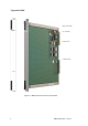
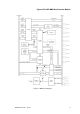
Triguard SC300E SW1 (not used) IC1 (FPGA) Connector J1 Connector J2 Figure 1-1 MBB General view and front panel detail 2 MBB October 2005 – Issue 4
Triguard SC300E MBB Bus Extender Module SPECIFICATION Model MBB Indicators Health Module power consumption 2.2W Overall size (mm) 400(9U)H x 397L x 28W Overall size (inches) 15.75H x 15.63L x 1.1W Weight 0.9kg ENVIRONMENTAL SPECIFICATIONS The maximum ambient temperature measured at the hottest point within the Triguard system shall not be greater than 60 degrees centigrade.
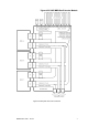
Triguard SC300E TECHNICAL DESCRIPTION PHYSICAL The MBB is a 9U high PCB with integral front panel. A general view is shown in Figure 1-1. DIP switch SW1 is inactive in the present application. EXTERNAL CONNECTIONS Each module is plugged into an extension chassis backplane bus system via two DIN41612 connectors J1 and J2 (Figure 1-1). The extension chassis backplane bus interconnections are shown in Figure 2-2.
Triguard SC300E MBB Bus Extender Module Figure 2-1 Local chassis interconnections Table 2-1. Connector location and type Connector Location Type J1 (I/O bus) MBB rear edge (Figure 1-1) 96-pin DIN 41612 type C male J2 (expansion bus) MBB rear edge (Figure 1-1) 96-pin DIN 41612 type c male e (expansion bus) Rear of backplane (Figure 2-2) 96-pin DIN 41612 type C female CONTROLS AND INDICATORS The MBB has no user controls.
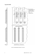
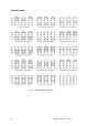
Triguard SC300E EXTENSION CHASSIS ADDRESSING The chassis address is set up on links on the chassis backplane. The physical locations of the links are indicated by small triangles in columns ‘b’ and ‘c’ of areas ‘d’ in Figure 2-3. On the chassis backplane the links are identified as UNIT ID0 to UNIT ID3. The presence of a link sets the corresponding address bit to ‘0’. If a link is absent the corresponding address bit is a ‘1’. The full range of chassis address link settings is given in Figure 2-5.
Triguard SC300E MBB Bus Extender Module Figure 2-2 Backplane bus interconnections MBB October 2005 – Issue 4 7
Triguard SC300E 0 1 2 3 UNIT ID 0 1 2 3 UNIT ID 0 1 2 3 UNIT ID Figure 2-3 MBB Related backplane connectors 8 MBB October 2005 – Issue 4
Triguard SC300E MBB Bus Extender Module Figure 2-4 MBB -Block diagram MBB October 2005 – Issue 4 9
Triguard SC300E Figure 2-5 Chassis address link coding 10 MBB October 2005 – Issue 4
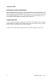
Triguard SC300E MBB Bus Extender Module SERVICING SCOPE The MBB is not field repairable. Field servicing operations are confined to the total replacement of faulty MBBs. Return faulty MBBs for repair. DIAGNOSIS A faulty MBB will be apparent by a single I/O channel failure affecting all the field devices serviced by a particular extension chassis. The Health LED may also extinguish. CONFIGURATION There are no on-board configurable links. Refer to section Figure 2-5 for chassis address link settings.
Triguard SC300E SERVICE SUPPORT SPARE PARTS Spare parts and technical advice may be obtained from your local area office.