
User guide
2
1. DISCONNECT AND LOCK OUT ALL INCOMING
DRIVE POWER TO THE MAXPAK PLUS CONĆ
TROLLER.
2. Remove
incoming line power connections from the
L1, L2 and L3 (181, 182 and 183) terminals of the
power
unit. Mark the wires with L1, L2 and L3 identi
Ć
fication as they are being removed. This is essential
to allow reconnection of line power in step 15 with
the same phase rotation. Failure to do so will reĆ
sult in a failure of the drive to run when reenerĆ
gized in step 17.
NOTE: It the controller has already been equipped
with a contactor cover kit, Model number 23C310,
Steps 3 through 7 below may be skipped.
Top and bottom mounting brackets installed as
part
of the contactor cover kit
will be used to support
the
circuit breaker
and its mounting panel. Proceed
to step 8.
3. It is first necessary to remove the bus bar support
noted
as <10 on sheet 2 of the assembly drawing.
Discard
the support once removed.
4. Locate the top mounting bracket and remove the
bus
bar support which is fastened to it
with two Phil
Ć
lips
head screws. The bus
bar support will be rein
Ć
stalled onto the top mounting bracket using these
screws
in a later step. See note <9 on sheet 2 of the
assembly drawing.
NOTE: A long (12 inch or longer) #2 Phillips
head
screwdriver with a magnetic tip is required
to
install the screws in steps 5 and 7 below
. It a
magnetic tipped Phillips head screwdriver of
this
length is not available, putty
, masking
tape,
or
some other
means should be used to hold the
screws on the tip of the screwdriver during
installation. Otherwise, they may drop into the
components on the auxiliary panel from where
they
might be difficult
to remove and where they
can pose a short circuit risk.
5. Using the 12 inch long Phillips head screwdriver
with #2 magnetic tip, install the top mounting
bracket
to the auxiliary panel using two
1/4Ć20 X 1/2
self
tapping screws.
6. Remount the busbar support to the top mounting
bracket
using the screws removed in step 4 above.
7. If necessary, remove the wire harness base which
dresses the auxiliary contact cable to the auxiliary
panel.
This base may occupy one of
the two mount
Ć
ing holes for the lower bracket. Mount the bottom
mounting bracket using two 1/4Ć20 x 1/2" self tapĆ
ping screws and the magnetic screwdriver. Once
the lower bracket is in place, the auxiliary harness
should
be secured to the lower bracket using the ty
Ć
rap
and base supplied with the kit. If any wires from
the auxiliary harness were disconnected to allow
easier installation of the bottom bracket, they
should
be reconnected at this time.
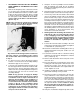
8. Warning:
Mount the
insulating side shield to the
right
side lip of the cover plate using three
#6Ć32
x
3/8" self tapping screws. This shield provides
personnel protection by preventing accidental
contact with otherwise hidden armature circuit
buswork. Its installation is required by N.E.C.
and U.L.
9. Connect the load side cable assembly to the load
side (bottom) circuit breaker terminals and tighten
to 125/140 Ib.Ćin. (1.44/1.6 kg.Ćm.)
10. Fasten
the circuit breaker mounting plate to the top
and bottom brackets using four 1/4Ć20 x 1/2" self
tapping
screws.
11. Connect
the load side cable to controller
incoming
terminals
181, 182 and 183 and tighten to 125/140
Ib.Ćin. (1.44/1.6 kg.Ćm.)
12. Remove and discard the small cover plate on the
enclosure
door
.
13. Close the cabinet door and verify the center of the
locking
pin on the C/B operator shaft at 15/32" from
the
inner door surface. If not, ad just to 15/32" and
then turn shaft CCW until slot is aligned with set
screw.
T
ighten set screw
.
14. Install
the circuit breaker handle to the door with the
gasket
and mounting screws provided.
15. Reconnect
incoming aĆc plant power to the line side
(top) terminations of the circuit breaker. Connect
the wire previously connected to power unit
termi
Ć
nal
L1 to the left side breaker terminal, the wire from
L2 to the center terminal and the wire previously
connected to power unit terminal L3 connected to
the right side breaker terminal. Failure to follow
this procedure may result in phase rotation reĆ
versal
and a failure of the drive to run when reen
Ć
ergized in step 17.
16. Verify
the circuit breaker magnetic trip units to L
O.