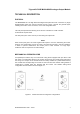
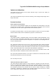
Triguard SC300E MAO04NND Analogue Output Module (MAO04NND) Issue 1 October 2005 INTRODUCTION PURPOSE The 4-Channel Analogue Output Module MAO04NND (Figure 1-1) provides analogue output signals. The module is a rack mounted, 9U high unit that provides the output control interface between the SC300E processing environment and the user field environment. It has four current loop output channels. All field outputs are galvanically isolated from the SC300E system but have a common supply connection.
Triguard SC300E 2 MAO04NND Octrober 2005 – Issue 1
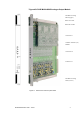
Triguard SC300E MAO04NND Analogue Output Module Mechanical coding Block (Upper) Links JP1 to JP4 Links LK1 to LK3 Connector J1 Common Interface (CI) Module Connector J2 Connector J3 Mechanical coding block (Lower) Figure 1-1 General view and front panel detail MAO04NND October 2005 – Issue 1 3
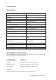
Triguard SC300E SPECIFICATION Model MAO04NND Channels 4 Architecutre TMR Indicators Health, 3 x On Line Test points 4 x signal, 1 x common Output range 0 to 22mA Maximum resistive field load 400 ohm Resolution 6.25 µA steps Accuracy @ 25°C +0.
Triguard SC300E MAO04NND Analogue Output Module MAO04NND October 2005 – Issue 1 5
Triguard SC300E TRANSPORT AND HANDLING The MAO04NND must be transported and stored in its original packing material which should be retained for this purpose.
Triguard SC300E MAO04NND Analogue Output Module TECHNICAL DESCRIPTION PHYSICAL The MAO04NND is a 9U high PCB with integral front panel and rear connectors. A plug-in daughterboard carries the common interface circuits. Figure 1-1shows the general layout, including the location of the connectors, covers and configuration links.
Triguard SC300E EXTERNAL CONNECTIONS All connections to the MAO04NND are made via DIN 41612 connectors. The upper connector is the system triple I/O bus connector. The middle connector is for the field inputs and outputs. The lower connector is electrically in parallel with the middle connector.
Triguard SC300E MAO04NND Analogue Output Module THEORY OF OPERATION The module has four 0-22mA current output channels using a common 24V supply via termination card TPH44AIC. The circuits are triplicated except for the final combining of the analogue output stages into a single voted output. Common functions Power supplies and monitoring The 5V and 12V dual-redundant supplies from the backplane are diode-OR’ed to the three channels plus an auxiliary section.
Triguard SC300E Voting operates so that the LFD deviations do not appear on the combined output. If a fault causes health to fail, no further LFD testing is performed.
Triguard SC300E MAO04NND Analogue Output Module Figure 2-2 Analogue output section - Schematic block diagram Analogue outputs Five test-sockets are provided for monitoring the output lines: one common terminal via 2.2k ohm to the +24V field supply, and the other four via 10k ohm to the current-determining resistors on the termination card. These resistors are 250 ohm, so 20mA of loop-current corresponds to 5V across them. The four analogue voltage outputs use 12-bit DACs to produce +0.
Triguard SC300E Common interface The three discrete control circuits in the common interface (A, B, and C) (Figure 2-3 ) are each responsible for the control of the corresponding one third of the I/O module circuits. Each control circuit comprises a microcontroller with a dedicated watchdog, data buffers and shared RAM. The circuit is powered via the module and permits live insertion of replacement modules.
Triguard SC300E MAO04NND Analogue Output Module Figure 2-3 Common interface - Block diagram MAO04NND October 2005 – Issue 1 13
Triguard SC300E SUPPLEMENTARY INFORMATION Connector J1 is the I/O bus. Field output connectors J2 and J3 are in parallel. The Channel connections are shown in Table 2-1. Table 2-1.
Triguard SC300E MAO04NND Analogue Output Module SERVICING SCOPE Repair is by module replacement. Faulty modules are not repairable in the field. They should be replaced by new modules and returned for repair. CAUTION 1 Before fitting a new module ensure that the setting of all links is the same as that on the old module. CAUTION 2 The module contains components that may be electrostatically sensitive, it should be transported and stored in its original packaging.
Triguard SC300E REMOVAL AND REPLACEMENT CAUTION 4 Failure to take the faulty module off-line before removing it from the chassis could trigger a fault alarm. CAUTION 5 When inserting a module ensure that it is aligned with the markings on the chassis rails and that it engages with the top and bottom guides. Improper insertion may cause damage to the module and/or chassis connectors. Single-slot hot repair CAUTION 6 Field loop current will not be supplied during changeover. 1.
Triguard SC300E MAO04NND Analogue Output Module 2. Operate the On/Off Line Request switch on the new module. Ascertain that the three On Line LEDs on the new module illuminate for one second, extinguish for one second and then illuminate permanently as the LEDs on the old module extinguish. This sequence indicates that the new module has been put on line and the old module taken off line.
Triguard SC300E SERVICE SUPPORT SPARES Spare parts and technical advice can be obtained from your local area offices.