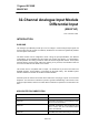
Triguard SC300E MAI32*AD 32-Channel Analogue Input Module Differential Input (MAI32*AD) Issue 4 October 2005 INTRODUCTION PURPOSE The Analogue Input Module provides up to 32, low voltage or current analogue input signals. All channel inputs into the module are resistively isolated from each other and galvanically isolated from the system environment.
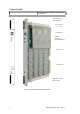
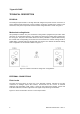
Triguard SC300E to DIN, 250 Ohm terminated, Internal power, User Manual Mechanicalcodin g block(Upper) 321/320 Link 321 320 ConnectorJ1 Common Interface (CI) (on daughterboard) Connector J2 Connector J3 Mechanical coding block (Lower) Figure 1-1 General view and front panel detail 2 MAI32*AD October 2005 – Issue 4
Triguard SC300E MAI32*AD 32-Channel A/I Module Differential Input SPECIFICATION Input parameters All models have 32 input channels configured as follows: Model number Voltage input applications MAI32LAD 0 to 5Vdc MAI32MAD 0 to 10Vdc Current input applications 0 to 20mA.
Triguard SC300E 4 MAI32*AD October 2005 – Issue 4
Triguard SC300E MAI32*AD 32-Channel A/I Module Differential Input NOTE For voltage loop inputs TAI16AEA termination cards must be used ENVIRONMENTAL SPECIFICATIONS The maximum ambient temperature measured at the hottest point within the Triguard system shall not be greater than 60 degrees centigrade.
Triguard SC300E TECHNICAL DESCRIPTION PHYSICAL The Analogue Input Module is a 9U high PCB with integral front panel and rear connectors; a plug-in daughter board carries the Common Interface circuits.The general layout, location of the connectors, front panel components and the 321/320 configuration link is shown in Figure 1-1.
Triguard SC300E MAI32*AD 32-Channel A/I Module Differential Input Figure 2-2 Basic field input circuit Figure 2-3 Field input using Termination Card MAI32*AD October 2005 – Issue 4 7
Triguard SC300E Figure 2-4 Field input connectors J2 and J3 pinouts Module connectors The System bus connector is J1 and the Common Interface is connected via J4 and J5 (not shown).
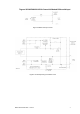
Triguard SC300E MAI32*AD 32-Channel A/I Module Differential Input THEORY OF OPERATION Analogue input module The first part of the block diagram in Figure 2-5 shows the circuit used to process one of the 32 analogue inputs. The field input is connected across a ranging resistor which is selected in accordance with the type of field input to be processed (current or voltage).
Triguard SC300E 10 MAI32*AD October 2005 – Issue 4
Triguard SC300E MAI32*AD 32-Channel A/I Module Differential Input Figure 2-5 Analogue input module- Block diagram MAI32*AD October 2005 – Issue 4 11
Triguard SC300E Common interface The three discrete control circuits in the Common Interface (A, B, and C) are each responsible for the control of the corresponding one third of the I/O module circuits. Each control circuit comprises a microcontroller with a dedicated watchdog, data buffers and shared RAM. The circuit is powered via the module and permits live insertion of replacement modules.
Triguard SC300E MAI32*AD 32-Channel A/I Module Differential Input SERVICING SCOPE System repair is by module replacement. Faulty modules are not repairable in the field, they should be replaced by new modules and returned for repair. CAUTION 1 Before fitting a new module ensure that the 321/320 link setting is the same as that on the old module. CAUTION 2 The module contains components that may be electrostatically sensitive, it should be transported and stored in its original packaging material.
Triguard SC300E CAUTION 5 When inserting a module ensure that it is aligned with the markings on the chassis rails and that it engages with the upper and lower guides. Improper insertion may cause damage to the module and/or chassis connectors. Single-slot hot repair Operate the On/Off Line Request switch on the faulty module, the three On Line LEDs should all go out to indicate that the MPPs have recognised the request and taken the module off-line.
Triguard SC300E MAI32*AD 32-Channel A/I Module Differential Input SERVICE SUPPORT SPARE PARTS Spare parts and technical advice can be obtained from the your local area office.