
Owner's manual


Publication LZ-UM001A-EN-P - January 2008
56 Specifications and Dimensions
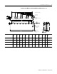
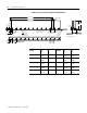
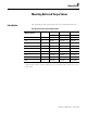
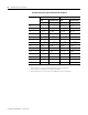
Magnet Channel Layout (Catalog Number LZM-100-HT-xxx)
Magnet Channel
Cat. No.
L
mm
(in.)
XHole
Quantity
Y
mm
(in.)
Flatness -A-
mm
(in.)
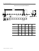
LZM-100-HT-120 119.0
(4.69)
1 2 95.0
(3.74)
0.13
(0.005)
LZM-100-HT-180 179.0
(7.05)
2 3 155.0
(6.10)
0.13
(0.005)
LZM-100-HT-240 239.0
(9.41)
3 4 215.0
(8.47)
0.13
(0.005)
LZM-100-HT-480 479.0
(18.86)
7 8 455.0
(17.91)
0.26
(0.010)
LZM-100-HT-600 599.0
(23.58)
9 10 575.0
(22.64)
0.26
(0.010)
0.25 (0.009)
A
0.25 (0.009)
B
M6 X 1.0-6H
See table for quantity
A
B
A
L ±0.25 (±.010)
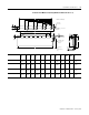
Mounting Hole Dimensions
60.00
(2.362)
Mounting Hole Dimensions
60.00
(2.362)
29.5
(1.16)
19.0
(0.75)
51.3
(2.02)
29.5
(1.16)
"X" Places
60.00
(2.362)
25.7
(1.01)
See table for quantity
Ø
THRU
5.7
(0.23)
125.00
(4.92)
131.0
(5.16)
17.5
(0.69)
9.5
(0.37)
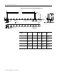
Y ±0.05 (±.002)
Setup Dimension
25.00
(0.984)
6.35 (0.25) DP
Both Sides
Ø
4.00
+0.06
0
(0.157
+0.002
-0.000
)
Ø
10.0
(0.39)
See Tabulation
Air gap will result from setting the plates to
setup dimensions shown.
Ø10.0
(0.39)
43.3
(1.71)
"X" Places
60.00
(2.362)
Dimension are in mm (in.)