
Owner's manual

Publication LZ-UM001A-EN-P - January 2008
50 Specifications and Dimensions
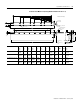
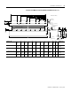
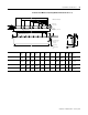
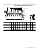
Magnet Channel Layout (Catalog Number LZM-075-HT-xxx)
Magnet Channel
Cat. No.
L
mm
(in.)
XHole
Quantity
Y
mm
(in.)
Flatness -A-
mm
(in.)
LZM-075-HT-120 119.0
(4.69)
1 2 95.0
(3.74)
0.13
(0.005)
LZM-075-HT--180 179.0
(7.05)
2 3 155.0
(6.10)
0.13
(0.005)
LZM-075-HT--240 239.0
(9.41)
3 4 215.0
(8.47)
0.13
(0.005)
LZM-075-HT--480 479.0
(18.86)
7 8 455.0
(17.91)
0.26
(0.010)
LZM-075-HT--600 599.0
(23.58)
9 10 575.0
(22.64)
0.26
(0.010)
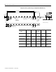
0.25 (0.009)
A
0.25 (0.009)
B
M6 X 1.0-6H
See table for quantity
A
B
A
L ±0.25 (±0.010)
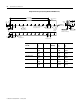
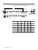
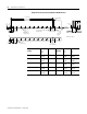
Mounting Hole Dimension
60.00
(2.362)
29.5
(1.16)
"X" Places
60.00
(2.362)
19.0
(0.75)
51.3
(2.02)
29.5
(1.16)
"X" Places
60.00
(2.362)
Mounting Hole Dimension
60.00
(2.362)
25.7
(1.01)
See table for quantity
Ø
THRU
5.8
(0.23)
100.0
(3.94)
106.0
(4.17)
17.5
(0.69)
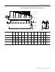
Y ±0.05 (±0.002)
Setup Dimension
25.00
(0.984)
9.5
(0.37)
Ø
6.35 (0.25) DP
Both Sides
4.00
+0.06
0
(0.157
+0.002
-0.000
)
Ø
(10.0)
(0.39)
See Tabulation
Air gap will result from setting the plates to
setup dimension shown.
Ø10.0
(0.39)
43.3
(1.71)
Dimension are in mm (in.)