
Owner's manual

Publication LZ-UM001A-EN-P - January 2008
18 Installation
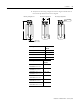
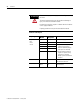
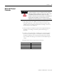
Motor Phasing Diagram
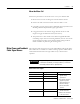
Back EMF Voltage vs. Hall Signals
Phasing direction = the coil toward motor power cable for moving coil
configuration as shown in Positive Motor Direction or the magnet assembly
away from power cable for moving magnet configuration.
Positive Motor Direction
When properly wired this is considered the positive direction.
0° 60° 120° 180°
240°
300°
360°
S1
S2
S3
Back
EMF
Voltage
Digital
Hall
Signals
Linear Travel mm (in.)
U-V
W-U
V-W
60 (2.36)
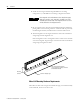
Coil Motion
Stationary Magnet