
Owner's manual

Publication LZ-UM001A-EN-P - January 2008
Installation 13
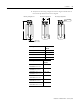
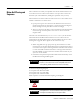
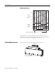
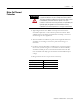
3. Verify that the mounting configuration for the magnet channel and coil
fits in envelope dimensions shown in diagram.
A
B
0.83
±
0.40
(0.033
±
0.015)
0.10 (.003)
Mounting Configuration A Mounting Configuration B Mounting Configuration C
Catalog Number A
mm (in.)
LZM-030-
x-xxx-x-x-x-x-x 80.0 (3.15)
LZM-050-
x-xxx-x-x-x-x-x 100.0 (3.94)
LZM-075-
x-xxx-x-x-x-x-x 130.0 (5.12)
LZM-100-
x-xxx-x-x-x-x-x 155.0 (6.10)
Catalog Number B
mm (in.)
LZM-030-0-
xxx-x-x-x-x-x
LZM-050-0-xxx-x-x-x-x-x
36.4 (1.43)
LZM-030-T-
xxx-x-x-x-x-x
LZM-050-T-xxx-x-x-x-x-x
37.7 (1.48)
LZM-030-HT-
xxx-x-x-x-x-x
LZM-050-HT-xxx-x-x-x-x-x
43.15 (1.70)
LZM-075-0-
xxx-x-x-x-x-x
LZM-100-0-xxx-x-x-x-x-x
38.05 (1.50)
LZM-075-T-
xxx-x-x-x-x-x
LZM-100-T-xxx-x-x-x-x-x
39.35 (1.55)
LZM-075-HT-
xxx-x-x-x-x-x
LZM-100-HT-xxx-x-x-x-x-x
43.15 (1.70)