ANORAD LZ Series Linear Motors USER MANUAL Publication LZ-UM001A-EN-P January 2008
Important User Information Solid state equipment has operational characteristics differing from those of electromechanical equipment. Safety Guidelines for the Application, Installation and Maintenance of Solid State Controls, publication SGI-1.1, available from your local Rockwell Automation sales office or online at http://literature.rockwellautomation.com. It describes some important differences between solid state equipment and hard-wired electromechanical devices.
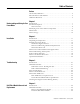
Table of Contents Preface About This Publication . . . . . . . . . . . . . . . . . . . . . . . . . . . . . . . . . . . . . . 5 Who Should Use This Manual. . . . . . . . . . . . . . . . . . . . . . . . . . . . . . . . . 5 Additional Resources . . . . . . . . . . . . . . . . . . . . . . . . . . . . . . . . . . . . . . . . 5 Chapter 1 Understanding and Caring for Your Introduction . . . . . . . . . . . . . . . . . . . . . . . . . . . . . . . . . . . . . . . . . . . . . . . 7 Product Description. . . . . . . .
Appendix A Specifications and Dimensions Introduction . . . . . . . . . . . . . . . . . . . . . . . . . . . . . . . . . . . . . . . . . . . . . . 31 Trapezoidal Hall Effect Circuit . . . . . . . . . . . . . . . . . . . . . . . . . . . . 32 Positive Temperature Coefficient (PTC) Thermistor . . . . . . . . . . 32 Environmental Specifications for LZ Linear Motors . . . . . . . . . . 32 LZ Series Linear Motor Dimensions. . . . . . . . . . . . . . . . . . . . . . . . . . .
Preface Read this preface to familiarize yourself with the manual. About This Publication This manual provides detailed installation instructions for mounting, wiring, maintaining, and troubleshooting your LZ Linear Motor. Who Should Use This Manual This manual is intended for engineers or technicians directly involved in the installation, wiring, and maintenance of this LZ linear motor.
Publication LZ-UM001A-EN-P - January 2008
Chapter 1 Understanding and Caring for Your Linear Motor Introduction Product Description The LZ Linear Motor Series description and maintenance is given in this section. Product features are explored and the part numbering system is explained. This information will help you develop an understanding of the linear motor’s basic configuration.
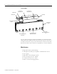
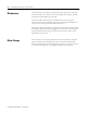
Understanding and Caring for Your Linear Motor LZ Linear Motor Coil Power Cable Coil Assembly Top Mounting Holes (x 4) Coil Assembly Side Mounting Holes (x 2) Coil Assembly Thermistor Cable Hall Effect Module (Optional) Magnet Channel Assembly Never attempt to disassemble magnet channel Through Holes for mounting Magnet Channel Assembly For use with Magnet Channel Alignment Tool (x2) For servo drives that require commutation feedback, an optional trapezoidal (digital) Hall effect feedback modu
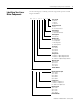
Understanding and Caring for Your Linear Motor Identifying Your Linear Motor Components 9 Use the following key to identify your linear stage and its options coil and magnet assemblies.
Understanding and Caring for Your Linear Motor Maintenance Anorad linear motors require no maintenance when operated in a relatively clean environment. For operation in harsh and dirty environments, minimal cleaning is recommended every 6 months. Clean the metallic debris and other contaminants from the air gap. To effectively remove the metal debris use a strip of masking tape. Simply put a strip of tape in the magnet channel and then remove it.
Chapter 2 Installation Introduction Unpacking and Inspection Use the following section to guide you through installation and start-up of your LZ linear motor. Topic Page Unpacking and Inspection 12 Installing the Linear Motor 12 Motor Power and Feedback Cable Signal Names 15 Motor-Hall Phasing and Sequence 17 Positive Motor Direction 18 Motor Coil Thermal Protection 19 Operational Guidelines 20 Inspect motor assemblies for damage that may have occurred in shipment.
Installation Installing the Linear Motor Use the following procedures to install the magnet channel and the motor coil to create a linear motor. Mount the Magnet Channel The required tools are: • magnet channel alignment tool (supplied). • aluminum straight edge. • non-magnetic M4 or M5 hex wrench. Use M6 SHCS for channel mounting configuration A, or M5 SHCS for channel mounting configuration B and C see diagram on page 14. See Specifications and Dimensions starting on page 31 for quantity.
Installation 13 3. Verify that the mounting configuration for the magnet channel and coil fits in envelope dimensions shown in diagram. Mounting Configuration A Mounting Configuration B B Mounting Configuration C 0.10 (.003) A 0.83 ± 0.40 (0.033 ± 0.015) Catalog Number A mm (in.) LZM-030-x-xxx-x-x-x-x-x 80.0 (3.15) LZM-050-x-xxx-x-x-x-x-x 100.0 (3.94) LZM-075-x-xxx-x-x-x-x-x 130.0 (5.12) LZM-100-x-xxx-x-x-x-x-x 155.0 (6.10) Catalog Number B mm (in.
Installation 4. Install the first magnet channel using M6 SHCS for mounting configuration A, or M5 SHCS for mounting configuration B and C. TIP Non-magnetic tools and hardware such as beryllium copper, 300 series stainless steel, and others should be used. If not available, proceed carefully since magnetic and ferrous items will be attracted to the magnet channel. 5. Do not tighten bolts at this time.
Installation 15 Mount the Motor Coil Follow these procedures to mount the motor coil to your machine slide. 1. Be sure the motor coil mounting face is clean and free of burrs. 2. Position the slide at the end of travel where the cable is to exit. 3. Using M4 x 0.7 bolts with a length as defined by previously in Motor Coil Mounting Hardware Requirements. Lightly tighten bolts. 4. Using plastic shim stock measure the gap between the motor and magnet. The gap should be 0.83 ± 0.4 (0.033 ± 0.15). 5.
Installation ATTENTION Disconnect the input power supply before installing or servicing the motor. The motor lead connections can short and cause damage or injury if not well secured and insulated. Insulate the connections, equal to or better than the insulation on the supply conductors. Properly ground the motor per the selected drive manual.
Installation Motor-Hall Phasing and Sequence 17 The LZ linear motor family is compatible with off-the-shelf brushless motor servo drives. The servo drive will see them as a two-pole motor with a full electrical cycle of 60 millimeters (360 degrees equivalent rotary motion). The brushless motor drives and controls must have two control functions for suitable commutation of a linear motor.
Installation Motor Phasing Diagram Back EMF Voltage vs. Hall Signals W-U Back EMF Voltage U-V V-W S1 Digital Hall Signals S2 S3 0° 60° 120° 180° 240° 300° 360° Linear Travel mm (in.) 60 (2.36) Phasing direction = the coil toward motor power cable for moving coil configuration as shown in Positive Motor Direction or the magnet assembly away from power cable for moving magnet configuration. Positive Motor Direction When properly wired this is considered the positive direction.
Installation Motor Coil Thermal Protection ATTENTION 19 LZ linear motors with the thermal protection option will supply a signal that indicates the motor temperature limit condition. This signal should be used by the motor control or drive system to immediately shut down the motor power on an open condition. Since linear motors are generally not repairable, and typically highly integrated into the mechanical structure, redundant motor thermal protection is strongly recommended.
Installation Operational Guidelines After installing the motor and before powering up your system for the first time, performed the Motor Coil Electrical Test on page 23 to verify motor condition. ATTENTION Moving parts can injure. Before running the motor, make sure all components are secure and the magnet mounting hardware is below magnet surface.
Chapter 3 Troubleshooting Introduction Hall Effect Module Use this section to diagnose the health of motor coil and the Hall effect module. Topic Page Hall Effect Module 21 PTC Thermal Signal 22 Motor Coil Electrical Test 23 Motor Back EMF Tests 24 Checking the Magnet Channel Butting Polarity 26 Use the following procedures to troubleshoot the Hall effect module.
Troubleshooting 6. Check for the proper logic levels (approximately 0V = low, +V = high) and the sequence: S1 leads S2 leads S3 with approximately 120 electrical degree spacing in between. TIP Connect the probe common to the Hall signal common. Hall to Back EMF Phasing 1. Turn the drive power OFF. 2. Verify the Hall circuit is connected to the drive per interface wiring specifications. 3. Disconnect the motor leads from the drive. 4. Turn the Hall power supply ON (driver power ON). 5.
Troubleshooting Motor Coil Electrical Test 23 Perform this test after installation and when a coil electrical fault is suspected. ATTENTION Dangerous voltages, forces and energy levels exist in servo controlled systems. Extreme care must be exercised when operating, maintaining or servicing the linear motor to prevent harm to personnel or equipment 1. Ensure the coil is at room temperature, approximately 25 oC (77 oF). 2. Turn the drive power OFF. 3.
Troubleshooting 7. Compare the phase resistance readings to the cold resistance specification of the specific coil model. The three reading should be about the same and comparable to the cold resistance specified for your model. When the coil is hot the resistance reading should still be balanced and but may be as mush as 30 … 40% higher than the cold resistance. To rule out the cable resistance, disconnect the field cable at the coil assembly interface and repeat the procedures at the coil.
Troubleshooting 25 5. Repeat step 4 comparing V-W to U-W. In this case U-W should lead V-W by 60o. The shapes and peak voltages should be approximately the same. Note that probe common = W. Be sure to use the same phasing direction as in step 4. Check Measured Back EMF to Specification By comparing your measured and calculated Back EMF constant to the motor’s specified back EMF constant, you can verify the correct installation and general health of the magnets and coil.
Troubleshooting Mechanical displacement of one electrical cycle = motor magnetic pitch (180o) in inches multiplied by two. Note that the published specification may already be in “cycles.” In this case do not multiply by two. Use the following equation to calculate back EMF constant: mechanical displacement of one cycle (in) = velocity in ---------------------------------------------------------------------------------------------------------s cycle time (s) Vptz = V(pK-pK) x 0.
Troubleshooting 27 5. Using an oscilloscope, connect one channel between any Hall signal (output) and the Hall signal common. 6. Slowly and steadily move the motor by hand in one direction over the whole travel. Monitor the waveshape as you are doing this. The Hall signal should alternate between a high and low DC level of equal duty cycle (squarewave), as the Hall module passes over the alternating polarity magnets. Especially at the magnet channel joints, ensure the squarewave shape is consistent.
Troubleshooting Publication LZ-UM001A-EN-P - January 2008
Chapter 4 Hall Effect Module Removal and Replacement Introduction Hall Effect Module Use this section to change the Hall effect module. Topic Page Hall Effect Module 29 If a problem is detected with a Hall effect module use the following procedures to remove and replace the unit. The following procedures require a 3 mm hex key, non-magnetic preferred, and cardboard to fit in magnet channel. Replacement Hall Effect Modules Coil Catalog No.
Hall Effect Module Removal and Replacement 2. Place the module at the end of the motor with the sensor blade inserted in the magnet channel. 3. Install the two M4 SHCS using a 3 mm hex key. Do not over tighten. 4. Remove the cardboard from the magnet channel. 5. Connect the Hall cable connector.
Appendix A Specifications and Dimensions Introduction 31 Anorad/Rockwell Automation publication listed in Additional Resources on page 5 may supersede the information in this appendix.
Specifications and Dimensions Trapezoidal Hall Effect Circuit Description Specifications Input Power 5…24V dc, 20 mA max. Output NPN, open collector, 10 mA max. Hall signal common • Trapezoidal Hall Signals, 120o Spacing, Open Collector Transistor (24V max.) Outputs (Pull-up Resistor External) • Consult the drive manual or supplier for specific wiring instructions to the drive. Wiring is phase-commutation sensitive.
Specifications and Dimensions LZ Series Linear Motor Dimensions 33 Linear motors are designed to metric dimensions. Inch dimensions are conversions from millimeters. Untolereated dimensions are for reference. LZ Series Linear Motor Coil (Catalog Number LZ-030-0-xxx-x-0-x-x-x) F E D Dimension are in mm (in.) C B A 80.00 (3.15) 35.00 (1.38) 28.00 (1.10) Thermistor Wires 0.25mm2 (24 GA) 26.00 (1.02) Mounting Holes M4 X 0.7 X 8.5 mm Deep Quantity A1 - See table 4.50 (0.18) Power Cable Ø6.1 mm (0.
Specifications and Dimensions LZ Linear Motor Magnet Channel (Catalog Number LZM-030-0-xxx) L ±0.25 (±0.010) 25.00 Setup Dimension (0.984) Y ±0.05 (±0.002) 14.0 9.50 (0.55) (0.374) Ø (10.0) (0.39) 55.0 (2.17) 56.1 (2.21) See Tabluation 17.5 (0.69) 29.5 (1.16) 60.00 (2.362) "X" Places Ø 5.8 THRU (0.23) Ø10.0 31.5 (0.39) (1.24) See table for quantity 60.00 (2.362) Mounting Hole Dimension Air gap will result from setting the plates to setup dimension shown. Ø 4.00 +0.06 0 (0.157 +0.002 -0.
Specifications and Dimensions 35 LZ Series Linear Motor Coil (Catalog Number LZ-030-T-xxx-x-0-x-x-x) F E D Dimension are in mm (in.) C B A 80.00 (3.15) 35.00 (1.38) 28.00 (1.10) Thermistor Wires 0.25mm2 (24) GA 26.00 (1.02) Mounting Holes M4 X 0.7 X 8.5 mm Deep Quantity A1 - See table 4.50 (0.18) Power Cable Ø6.1 mm (0.24), 0.75 mm2 (18 GA) (Flying Leads) L Optional Hall Effect Module Ø6 mm (0.24) Cable (Flying Leads) A "G" Mounting Holes M4 X 0.7 X 7 mm Deep Typ.
Specifications and Dimensions Magnet Channel Layout (Catalog Number LZM-030-T-xxx) L ±0.25 (±0.010) 25.00 Setup Dimensions (0.984) Y ±0.05 (±0.002) 14.0 9.5 (0.55) (0.37) Ø (10.0) (0.39) 55.0 (2.17) 56.0 (2.21) See Tabulation 17.5 (0.69) 29.5 (1.16) 60.00 (2.362) "X" Places Ø 5.8 THRU (0.23) Ø10.00 34.1 (0.39) (1.34) See table for quantity Air gap will result from setting the plates to setup dimension shown. Ø 4.00 +0.06 0 (0.157 +0.002 -0.000 ) 60.00 (2.362) Mounting Hole Dimension A B 0.
Specifications and Dimensions 37 LZ Series Linear Motor Coil (Catalog Number LZ-030-HT-xxx-x-0-x-x-x) F E D Dimension are in mm (in.) C B A 80.00 (3.15) 35.00 (1.38) 28.00 (1.10) Thermistor Wires 0.25mm2 (24) GA 26.00 (1.02) Mounting Holes M4 X 0.7 X 8.5 mm Deep Quantity A1 - See table 4.50 (0.18) Power Cable Ø6.1 mm (0.24), 0.75 mm2 (18 GA) (Flying Leads) L Optional Hall Effect Module Ø6 mm (0.24) Cable (Flying Leads) A "G" Mounting Holes M4 X 0.7 X 7 mm Deep Typ.
Specifications and Dimensions Magnet Channel Layout Drawing (Catalog Number LZM-030-HT-xxx) L ±0.25 (±0.010) 25.00 Setup Dimension (0.984) Y ±0.05 (±0.002) 14.0 9.5 (0.55) (0.37) Ø (10.0) (0.39) 55.0 (2.17) 56.0 (2.21) See Tabulation 17.5 (0.70) 29.5 (1.16) 60.00 (2.362) "X" Places Ø 5.8 THRU (0.23) Ø10.0 43.3 (0.39) (1.71) See table for quantity Air gap will result from setting the plates to setup dimension shown. Ø 4.00 +0.06 0 (0.157 +0.002 -0.000 ) 6.35 (.25) DP Both Sides 60.00 (2.
Specifications and Dimensions 39 LZ Series Linear Motor Coil (Catalog Number LZ-050-0-xxx-x-0-x-x-x) F E Dimension are in mm (in.) D C B A 80.00 (3.15) 35.00 (1.38) 28.00 (1.10) Thermistor Wires 0.25 mm2 24 GA 26.00 (1.02) Mounting Holes M4 X 0.7 X 8.5 mm Deep Quantity A1 - See table 4.50 (0.18) L G 60.00 (2.362) Mounting Holes M4 X 0.7 X 7 mm Deep Typ. Both Sides Quantity A2 - See table Power Cable Ø 6.1 mm (0.24), 0.75 mm2 (18 GA) (Flying Leads) Optional Hall Effect Module Ø 6mm (0.
Specifications and Dimensions Magnet Channel Layout (Catalog Number LZM-050-0-xxx) L ±0.25 (±0.010) 25.00 Setup Dimension ( 0.984) Y ±0.05 (±0.002) 14.0 9.5 (0.55) (0.37) Ø(10.00) (0.394) 75.00 76.0 (2.95) (2.99) See Tabulation 17.5 (0.689) 29.5 (1.16) 60.00 (2.362) "X" Places Ø 5.75 THRU (0.226) Ø10.00 31.5 (0.394) (1.24) See table for quantity Air gap will result from setting the plate to the setup dimension shown. A Ø4.00 +0.06 0 +0.002 (0.157 -0.000 ) 6.36 (0.25) DP Both Sides 60.00 (2.
Specifications and Dimensions 41 LZ Series Linear Motor Coil (Catalog Number LZ-050-T-xxx-x-0-x-x-x) F E D Dimension are in mm (in.) C B A 80.00 (3.15) 35.00 (1.38) 28.00 (1.10) Thermistor Wires 0.25 mm2 (24) GA 26.00 (1.02) Mounting Holes M4 X 0.7 X 8.5 mm Deep Qantity A1 - See table 4.50 (0.18) L G 60.00 (2.362) Mounting Holes M4 X 0.7 X 7 mm Deep Typ. Both Sides Quantity A2 - See table Power Cable Ø 6.1 mm (0.24), 0.75 mm2 (18 GA) (Fliying Leads) Optional Hall Effect Module Ø 6mm (0.
Specifications and Dimensions Magnet Channel Layout (Catalog Number LZM-050-T-xxx) L ±0.25 (±0.010) 25.00 Setup Dimension ( 0.984) Y ±0.05 (±0.002) 14.0 9.50 (0.55) (0.374) Ø(10.00) (0.394) 76.00 75.00 (2.992) (2.953) See Tabulation 17.50 (0.689) 29.5 (1.16) 20.2 (0.80) 29.5 (1.16) 60.00 (2.362) "X" Places Ø 5.75 THRU (0.226) Ø10.00 34.1 (0.394) (1.34) See table for quantity 60.00 (2.362) Mounting Hole Dimension Air gap will result from setting the plate to the setup dimension shown. Ø4.
Specifications and Dimensions 43 LZ Series Linear Motor Coil (Catalog Number LZ-050-HT-xxx-x-0-x-x-x) F E D Dimension are in mm (in.) C B A 80.00 (3.15) 35.00 (1.38) 28.00 (1.10) Thermistor Wires 0.25 mm2 (24) GA 26.00 (1.02) Mounting Holes M4 X 0.7 X 8.5 mm Deep Qantity A1 - See table 4.50 (0.18) L G 60.00 (2.362) Mounting Holes M4 X 0.7 X 7 mm Deep Typ. Both Sides Quantity A2 - See table Power Cable Ø 6.1 mm (0.24), 0.75 mm2 (18 GA) (Fliying Leads) Optional Hall Effect Module Ø 6mm (0.
Specifications and Dimensions Magnet Channel Layout (Catalog Number LZM-050-HT-xxx) L ±0.25 (±0.010) 25.00 Setup Dimension ( 0.984) Y ±0.05 (±0.002) 14.0 9.5 (0.55) (0.37) Ø(10.0) (0.39) 76.0 75.0 (2.99) (2.95) See Tabulation 17.5 (0.69) 29.5 (1.16) 25.7 (1.01) 29.5 (1.16) 60.00 (2.362) "X" Places Ø 5.75 THRU (0.226) Ø10.00 43.3 (0.394) (1.71) See table for quantity Ø4.00 +0.06 0 (0.157 +0.002 -0.000 ) 6.36 (.25) DP Both Sides 60.00 (2.
Specifications and Dimensions 45 LZ Series Linear Motor Coil (Catalog Number LZ-075-0-xxx-x-0-x-x-x) F E D Dimension are in mm (in.) C B A 80.0 (3.15) 35.0 (1.38) Thermistor Wires 0.25 mm2 (24) GA 28.0 (1.10) 26.0 (1.02) 4.5 (0.18) Power Cable Ø6.1 mm (0.24), 0.75 mm2 (18 GA) (Flying Leads) Mounting Holes M4 X 0.7 X 8.5 mm Deep Quantity A1 - See table L G Mounting Holes M4 X 0.7 X 7 mm Deep Typ. Both Sides Quantity A2 - See table 60.00 (2.362) 38.00 (1.496) A A 22.0 (0.87) SEE CHART 11.
Specifications and Dimensions Magnet Channel Layout Drawing (Catalog Number LZM-075-0-xxx) L ±0.25 (±0.010) Y ±0.05 (±0.002) 25.00 Setup Dimension (0.984) 19.0 9.5 (0.75) (0.37) 106.0 100.0 (4.17) (3.94) Ø (10.0) (0.39) See Tabulation 17.5 (0.69) 29.5 (1.16) 60.00 (2.362) "X" Places Ø 5.8 THRU (0.23) Ø10.0 34.8 (0.39) (1.37) See table for quantity Ø4.00+0.06 0 (0.157 +0.002 ) -0.000 6.35 (.25) DP Both Sides 60.00 (2.
Specifications and Dimensions 47 LZ Series Linear Motor Coil (Catalog Number LZ-075-T-xxx-x-0-x-x-x) F E D Dimension are in mm (in.) C B A 80.0 (3.15) 35.00 (1.38) Thermistor2 Wires 0.25 mm (24) GA 28.0 (1.10) 26.00 (1.02) 4.50 (0.18) Power Cable Ø 6.1 mm (0.24), 0.75 mm2 (18 GA) (Flying Leads) Mounting Holes M4 X 0.7 X 8.5 mm Deep Quantity A1 - See table L G Mounting Holes M4 X 0.7 X 7 mm Deep Typ. Both Sides Quantity A2 - See table 60.00 (2.362) 38.00 (1.496) A A See Table 22.0 (0.87) 11.
Specifications and Dimensions Magnet Channel Layout (Catalog Number LZM-075-T-xxx) L ±0.25 (±.010) Y ±0.05 (±.002) 25.00 Setup Dimension (0.984) 19.0 9.5 (0.75) (0.37) 106.0 100.0 (4.17) (3.94) Ø(10.0) (0.39) See Tabulation 17.5 (0.69) 29.5 (1.16) 60.00 (2.362) "X" Places Ø 5.8 THRU (0.23) Ø10.0 37.4 (0.39) (1.47) See table for quantity Air gap will result from setting the plate to setup dimension shown. 60.00 (2.362) Mounting Hole Dimension Ø4.00+0.06 0 (0.157 +0.002 ) -0.000 6.35 (0.
Specifications and Dimensions 49 LZ Series Linear Motor Coil (Catalog Number LZ-075-HT-xxx-x-0-x-x-x) F E D Dimension are in mm (in.) C B A 80.0 (3.15) 35.00 (1.38) Thermistor2 Wires 0.25 mm (24) GA 28.0 (1.10) 26.00 (1.02) 4.50 (0.18) Power Cable Ø 6.1 mm (0.24), 0.75 mm2 (18 GA) (Flying Leads) Mounting Holes M4 X 0.7 X 8.5 mm Deep Quantity A1 - See table L G Mounting Holes M4 X 0.7 X 7 mm Deep Typ. Both Sides Quantity A2 - See table 60.00 (2.362) 38.00 (1.496) A A See Table 22.0 (0.
Specifications and Dimensions Magnet Channel Layout (Catalog Number LZM-075-HT-xxx) L ±0.25 (±0.010) Y ±0.05 (±0.002) 25.00 Setup Dimension (0.984) 19.0 9.5 (0.75) (0.37) 106.0 100.0 (4.17) (3.94) Ø (10.0) (0.39) See Tabulation 17.5 (0.69) 29.5 (1.16) 60.00 (2.362) "X" Places Ø 5.8 THRU (0.23) Ø10.0 43.3 (0.39) (1.71) See table for quantity Air gap will result from setting the plates to setup dimension shown. Ø4.00+0.06 0 (0.157 +0.002 ) -0.000 6.35 (0.25) DP Both Sides 60.00 (2.
Specifications and Dimensions 51 LZ Series Linear Motor Coil (Catalog Number LZ-100-0-xxx-x-0-x-x-x) F E D Dimension are in mm (in.) C B A 80.00 (3.15) 35.00 (1.38) Thermistor Wires 0.25 mm2 (24 GA) 28.00 (1.10) 26.00 (1.02) POWER CABLE Ø 6.1 mm (0.24), 0.75 mm2 (18 GA) (Flying Leads) Mounting Holes M4 X 0.7 X 8.5 mm Deep Quantity A1 - See table L G Mounting holes M4 X 0.7 X 7 mm Deep Typ. Both Sides Quantity A2 - See table 4.50 (0.18) 60.00 (2.362) 38.00 (1.496) A A 22.0 (0.
Specifications and Dimensions Magnet Channel Layout (Catalog Number LZM-100-0-xxx) L ±0.25 (±0.010) 25.00 Setup Dimension (0.984) Y±0.05 (±0.002) 19.0 9.5 (0.75) (0.37) 131.0 125.0 (5.16) (4.92) Ø(10.0) (0.39) See Tabulation 17.5 (0.69) 29.5 (1.16) 60.00 (2.362) "X" Places 20.6 (0.81) 29.5 (1.16) Ø 5.7 THRU (0.23) Ø10.0 34.6 (0.39) (1.37) See table for quantity Air gap will result from setting the plate to setup dimension shown. A Ø4.00 +0.06 0 +0.002 (0.157 -0.000 ) 6.35 (0.
Specifications and Dimensions 53 LZ Series Linear Motor Coil (Catalog Number LZ-100-T-xxx-x-0-x-x-x) F E Dimension are in mm (in.) D C B A 80.00 (3.15) Thermistor Wires 0.25mm2 (24) GA 28.00 (1.10) 35.00 26.00 (1.38) (1.02) Power Cable Ø 6.1 mm (0.24), 0.75 mm2 (18 GA) (Flying Leads) Mounting Holes M4 X 0.7 X 8.5 mm Deep Quantity A1 - See Table L G Mounting HolesM4 X 0.7 X 7 mm Deep Typ. Both Sides Quantity A2 - See Table 4.50 (0.18) 60.00 (2.362) 38.00 (1.496) A A 22.0 (0.87) See Table 11.
Specifications and Dimensions Magnet Channel Layout (Catalog Number LZM-100-T-xxx) L ±0.25 (±0.010) 25.00 Setup Dimension (0.984) Y ±0.05 (±0.002) 131.0 125.00 (5.16) (4.92) 19.0 9.5 (0.75) (0.37) Ø(10.0) (0.39) See Tabulation 17.5 (0.69) 29.5 (1.16) 60.00 (2.362) "X" Places 21.9 (0.86) 29.5 (1.16) Ø 5.7 THRU (0.23) Ø10.0 37.4 (0.39) (1.47) See table for quantity Air gap will result from setting the plates to setup dimension shown. Ø4.00 +0.06 0 (0.157 +0.002 -0.000 ) 6.35 (.
Specifications and Dimensions 55 LZ Series Linear Motor Coil (Catalog Number LZ-100-HT-xxx-x-0-x-x-x) F E D Dimension are in mm (in.) C B A 80.00 (3.15) Thermistor Wires 0.25mm2 (24) GA 28.00 (1.10) 35.00 26.00 (1.38) (1.02) Power Cable Ø 6.1 mm (0.24), 0.75 mm2 (18 GA) (Flying Leads) Mounting Holes M4 X 0.7 X 8.5 mm Deep Quantity A1 - See Table L G Mounting HolesM4 X 0.7 X 7 mm Deep Typ. Both Sides Quantity A2 - See Table 4.50 (0.18) 60.00 (2.362) 38.00 (1.496) A A 22.0 (0.87) See Table 11.
Specifications and Dimensions Magnet Channel Layout (Catalog Number LZM-100-HT-xxx) L ±0.25 (±.010) 25.00 Setup Dimension (0.984) Y ±0.05 (±.002) 19.0 9.5 (0.75) (0.37) 131.0 125.00 (5.16) (4.92) Ø 10.0 (0.39) See Tabulation 17.5 (0.69) 29.5 (1.16) 60.00 (2.362) "X" Places 25.7 (1.01) 29.5 (1.16) 60.00 (2.362) "X" Places Ø 5.7 THRU (0.23) Ø10.0 43.3 (0.39) (1.71) See table for quantity Air gap will result from setting the plates to setup dimensions shown. A 0.25 (0.009) B 51.3 (2.
Appendix B Mounting Bolts and Torque Values This appendix provides typical torque values for standard and metric bolts. Introduction Recommended Seating Torque for Metric Bolts Bolt Size (metric) (1) 57 Pitch Plain Cadmium Plated Zinc Nm (in-lb) Nm (in-lb) Nm (in-lb) M1.6 (2) 0.35 0.29 (2.6) 0.22 (1.95) 0.41(3.64) M2 (2) 0.40 0.60 (5.3) 0.45 (3.98) 0.84 (7.42) M2.5 (2) 0.45 1.24 (11) 0.93 (8.25) 1.74 (15.4) M3 0.5 2.15 (19) 1.61 (14.25) 3.00 (26.6) M4 0.7 4.6 (41) 3.
Mounting Bolts and Torque Values Recommended Seating Torque for Mild Steel Rb 87 or Cast Iron Rb 83 Bolt Size (1), (2) UNC UNF Plain Cadmium Plated Plain Cadmium Plated Nm (in-lb) Nm (in-lb) Nm (in-lb) Nm (in-lb) #0 – – 0.24 (2.1) (3) 0.18 (1.6) (3) #1 0.44 (3.89) (3) 0.53 (4.7) (3) 0.46 (4.1) (3) 0.34 (3.0) (3) #2 0.71 (6.3) (3) 0.53 (4.7) (3) 0.76 (6.8) (3) 0.58 (5.1) (3) #3 1.08 (9.6) (3) 0.81 (7.2) (3) 1.16 (10.3) (3) 0.87 (7.7) (3) #4 1.52 (13.5) (3) 1.
Mounting Bolts and Torque Values 59 Recommended Seating Torque for Brass Rb 72 Bolt Size (1), (2) UNC UNF Plain Cadmium Plated Plain Cadmium Plated Nm (in-lb) Nm (in-lb) Nm (in-lb) Nm (in-lb) #0 – – 0.24 (2.1) (3) 0.18 (1.6) (3) #1 0.43(3.8) (3) 0.33 (2.9) (3) 0.46 (4.1) 0.34 (3.0) (3) #2 0.71 (6.3) (3) 0.53 (4.7) (3) 0.77 (6.8) (3) 0.58 (5.1) (3) #3 1.08 (9.6) (3) 0.81 (7.2) (3) 1.16 (10.3) (3) 0.87 (7.7) (3) #4 1.52 (13.5) (3) 1.1 (10) (3) 1.67 (14.8) (3) 1.
Mounting Bolts and Torque Values Recommended Seating Torque for Aluminum Rb 72 (2024-T4) Bolt Size (1), (2) Publication LZ-UM001A-EN-P - January 2008 UNC UNF Plain Cadmium Plated Plain Cadmium Plated Nm (in-lb) Nm (in-lb) Nm (in-lb) Nm (in-lb) #0 - - 0.24 (2.1) (3) 0.18 (1.6) (3) #1 0.44 (3.8) (3) 0.33 (2.9) (3) 0.46 (4.1) (3) 0.34 3.0v #2 0.71 (6.3) (3) 0.53 (4.7) (3) 0.77 (6.8) (3) 0.58 (5.1) (3) #3 1.08 (9.6) (3) 0.81 (7.2) (3) 1.16 (10.3) (3) 0.87 (7.7) (3) #4 1.
Index A abrasives 12 accelerations 20 acetone 12 air gap 15, 20, 26 alignment tool 12 aluminum straight edge 12 attraction 14 magnetic 12 automatic implantable cardioverter defibrillator (AICD) 11 B back EMF 17, 18, 21, 26 cycle 25 measure 25 test 24 beryllium copper 14 brushless motor servo drives 17 C cable 8 cable length 9 channel length 9 cleaning 10 coil assembly 8 length 9 power cable 8 commutation 17 component locations 8 configuration 9 controller suitability 17 cooling 9 current max acceleration
Index H Hall effect module 8, 17 removal 29 replacement 29 feedback 9 troubleshooting 21 hardware requirements magnet channel 12 I inspection 11 installation 11 motor 12 motor coil 15 L logic levels 22 M magnet channel alignment 14 alignment tool 8, 14 assembly 8 magnet length 9 maintenance 10 max.
Index T temperature limit 19 thermal protection 9, 19 thermistor cable 8 through hole 8 TIR 12 tools 12 trapezoidal commutation 17 troubleshooting 21 Hall effect module 21 PTC thermal signal 22 63 U unpacking 11 W warning automatic implantable cardioverter defibrillator (AICD) 11 powerful forces 11 winding code 9 wire colors 15 witness marks 10 Publication LZ-UM001A-EN-P - January 2008
Anorad/Rockwell Automation 100 Precision Drive Shirley, NY 11967-4710 Web site http://www.anorad.com E-mail anorad@anorad.com Technical Support: Tel (631) 344-6600 Fax (631) 344-6660 email techsupport@anorad.com Anorad, Allen-Bradley, CompactLogix, DriveExplorer, Kinetix, RSLogix 5000, SoftLogix, SCANport, and Rockwell Automation are trademarks of Rockwell Automation, Inc. Trademarks not belonging to Rockwell Automation are property of their respective companies. www.anorad.com www.rockwellautomation.