
User Manual


Rockwell Automation Publication LX-UM001A-EN-P - March 2011 67
Interconnect Diagrams Appendix A
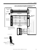
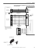
Figure 20 - Wiring Example for Ultra3000 Drive and LXxxxxxxxxHxx0x Linear Motor
with a Sin/Cos Encoder
W
V
U
W
V
U
COS+
COS-
SIN+
SIN-
IM+
IM-
POWER
COM
Green/Yellow
Black
White
Red
GND
W
V
U
TS+
TS -
Black
Black
White
Red
Black
Power
S1
S2
S3
COM
Blue
Orange
1
2
3
4
5
10
14
6
11
12
13
8
2090-UXBB-DM15
Cable Shield
Clamp
Note 1
Refer to low profile connector
illustration (lower left) for proper
grounding techniques.
Sin/Cos Encoder
LX-Series Linear Motor Coil
Three-phase
Motor Power
Hall Effect
Module
Wire as shown here using
cable type appropriate for
your application.
Linear Encoder
Thermal
Switch
Ultra3000 Drive
Motor Power
(TB1) Connector
Motor Feedback
(CN2) Connector
Motor Feed Breakout Board
Cable Tie
Ground techniques for
feedback cable shield.
Exposed shield secured
under clamp.