
User Manual

Rockwell Automation Publication LX-UM001A-EN-P - March 2011 59
Appendix
A
Interconnect Diagrams
Introduction
This appendix provides wiring examples to assist you in wiring an LX-Series
linear motor to an Allen-Bradley drive.
Wiring Examples
These notes apply to the wiring examples on the pages that follow.
Topic Page
Introduction 59
Wiring Examples 59
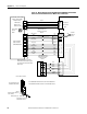
Wiring Example for Kinetix 6000, Kinetix 6500/6200 or Kinetix 2000
Drives and LXxxxxxxxxHxx1x Linear Motor with a TTL Encoder
60
Wiring Example for Kinetix 6000, Kinetix 6500/6200 or Kinetix 2000
Drives and LXxxxxxxxxHxx1x Linear Motor with a Sin/Cos Encoder
61
Wiring Example for Kinetix 6000, Kinetix 6500/6200 or Kinetix 2000
Drives and LXxxxxxxxxHxx0x Linear Motor with a TTL Encoder
62
Wiring Example for Kinetix 6000, Kinetix 6500/6200 or Kinetix 2000
Drives and LXxxxxxxxxHxx0x Linear Motor with a Sin/Cos Encoder
63
Wiring Example for Ultra3000 Drive and LXxxxxxxxxHxx1x Linear
Motor with a TTL Encoder
64
Wiring Example for Ultra3000 Drive and LXxxxxxxxxHxx1x Linear
Motor with a Sin/Cos Encoder
65
Wiring Example for Ultra3000 Drive and LXxxxxxxxxHxx0x Linear
Motor with a TTL Encoder
66
Wiring Example for Ultra3000 Drive and LXxxxxxxxxHxx0x Linear
Motor with a Sin/Cos Encoder
67
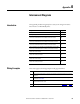
Note Information
1 Use the cable shield clamp to meet CE requirements. No external connection to ground is
required.
1 For motor cable specifications, refer to the Kinetix Motion Control Selection Guide,
publication GMC-SG001
.
2 TS + and TS - wires are black for LXxxxxxxxxxSxxx motor coils and red for
LXxxxxxxxxxTxxx motor coils.
3 When using the Sin/Cos encoder with Kinetix 6000 drives, refer to Appendix B
on page 69.