
User Manual


30 Rockwell Automation Publication LX-UM001A-EN-P - March 2011
Chapter 4 LX-Series Linear Motor Connector Data
Linear Motor Coil
Connectors
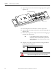
There are two connectors on the linear motor coil, catalog number
LXxxxxxxxNxxxx; the power connector and the thermal protection connector.
Power Connector
The following tables identifies the power signals for the DIN-style circular
connector.
Thermal Protection Connector
These are the feedback connector pinouts for the LX-Series linear motor, catalog
number LXxxxxxxxxxSxxx
.
These are the feedback connector pinouts for the LX-Series linear motor, catalog
number LXxxxxxxxxxTxxx.
Pin Color Signal
A Red U (A) Phase
B White V (B) Phase
C Black W (C) Phase
D Green/Yellow Ground
Case Shield
Cable Shield
and GND
ATTENTION: Properly ground the coil as described in this manual
and the drive manual.
Pin Description Signal
1 Thermal Switch + TS+
3 Thermal Switch - TS-
4– Reserved
Pin Description Signal
1 PTC thermistor + TS+
3 PTC thermistor - TS-
4– Reserved
Mating Connector Kit Allen-Bradley 2090-KPBM4-12AA
Intercontec P/N BKUA090NN00420220000
A
CB
D
E
H
L
F
G
1
4
3
1
4
3