
Manual


1-30 Installation/Wiring
Hard Enable Circuitry
A dedicated hardware enable input is provided on TB2 - Terminal 16
(Digital Input 6) for applications that require the drive to be disabled
without software interpretation.
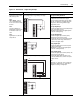
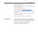
Input/Output Connection Example
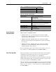
Digital Inputs - 24V dc Sourcing Digital Inputs - using internal power supply, 2-Wire
Control
Required Parameter Changes
• Set Parameter 829 [DigIn 5 Sel] to a value of 7
(Run).
• Parameter 153 [Control Options] bit 8
(3WireControl) will automatically be OFF for 2-wire
control.
• Set Parameter 168 [Normal Stop Mode] for the
desired stopping mode:
0 = Ramp Stop
1 = CurLim Stop
2 = Coast Stop
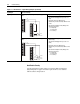
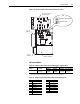
Sourcing Digital Inputs - using internal power supply, 3-Wire
Control
• Set Parameter 829 [DigIn 5 Sel] to a value of 14
(Normal Stop).
• Set Parameter 828 [DigIn 4 Sel] to a value of 5
(Start).
• Parameter 153 [Control Options] bit 8
(3WireControl) will automatically be ON for 3-wire
control.
• Set Parameter 168 [Normal Stop Mode] for the
desired stopping mode:
0 = Ramp Stop
1 = CurLim Stop
2 = Coast Stop
Figure 1.11 TB2 Terminals — Digital Wiring Examples (Continued)
24V DC
Com
RUN
Enable
1
2
3
4
5
6
7
8
9
10
11
12
13
14
15
16
24V DC
Com
START
Enable
STOP
1
2
3
4
5
6
7
8
9
10
11
12
13
14
15
16