
Manual

1-28 Installation/Wiring
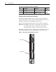
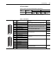
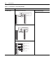
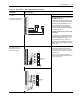
Table 1.J TB2 Terminals
Terminal Signal Description
Related
Parameter
1 24V dc Common (-) Drive supplied 24V dc logic input power
Rating: 300 mA maximum load
2 24V dc Source (+)
3 Digital Output 1 24V dc Open Collector (sinking logic)
Rating: Internal Source = 150 mA maximum
External Source = 750 mA
816, 847
4 Digital Output 1/2 Common Common for Digital Outputs 1 and 2
5 Digital Output 2 24V dc Open Collector (sinking logic)
Rating: Internal Source = 150 mA maximum
External Source = 750 mA
851, 852
6 Relay Output 3 (NC) Relay contact output
Rating: 115V ac or 24V dc = 2 A maximum Inductive/Resistive
856, 857
7 Relay Output 3 Common
8 Relay Output 3 (NO)
9 Digital Input 1-3 Common Common for Digital Inputs 1, 2, and 3
10 Digital Input 1 High speed 12-24V dc sourcing Digital Input
Load: 15 mA at 24V dc
825
11 Digital Input 2 826
12 Digital Input 3 Load: 15 mA at 24V dc sourcing 827
13 Digital Input 4-6 Common Common for Digital Inputs 4, 5, and 6
14 Digital Input 4 Load: 10 mA at 24V dc sinking/sourcing
Load: 7.5 mA at 115V ac
828
15 Digital Input 5 829
16 Digital Input 6 (HW Enable) 830
9
10
11
12
13
14
15
16
1
2
3
4
5
6
7
8