
Manual

Installation/Wiring 1-25
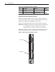
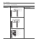
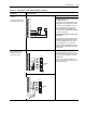
I/O Terminal Blocks
Table 1.H Main Control Board I/O Terminal Block Specifications
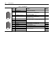
Table 1.I TB1 Terminals
Name Description
Wire Size Range
(1)
(1)
Maximum/minimum that the terminal block will accept - these are not recommendations.
Torque
Maximum Minimum Maximum Recommended
I/O Blocks Signal and encoder
power connections
1.5 mm
2
(16 AWG)
0.14 mm
2
(28 AWG)
0.25 N-m
(2.2 lb.-in.)
0.22 N-m
(1.9 lb.-in.)
Terminal Signal Description
Related
Parameter
1 Analog Input 1 Common Bipolar, differential input, +/-10V, 0-20 mA, 13 bit + sign
20K ohm impedance at Volt; 500 ohm impedance at mA
2 Analog Input 1 (+/-) 800
3 Shield Analog Input Shield
4 Analog Input 2 Common Bipolar, differential input, +/-10V, 0-20 mA, 13 bit + sign
20K ohm impedance at Volt; 500 ohm impedance at mA
5 Analog Input 2 (+/-) 806
6 Analog Input 3 [NTC-] Common Differential input, 0-10V, 10 bit (for motor control mode FVC2,
this is the temperature adaptation input).
7 Analog Input 3 [NTC+] 812
8 Shield Analog Output Shield
9 Analog Output 1 (-) Bipolar, differential input, +/-10V, 0-20 mA, 11 bit + sign
2K ohm minimum load
832, 833
10 Analog Output 1 (+)
11 Analog Output 2 (-) 839, 840
12 Analog Output 2 (+)
13 +10V Reference Rating: 20 mA maximum load (recommend 5K ohm
potentiometer)
14 Reference Common
15 -10V Reference
16 Encoder A Normal current draw per channel: 20 mA 230-233
17 Encoder A (Not)
18 Encoder B
19 Encoder B (Not)
20 Encoder Z
21 Encoder Z (Not)
22 Encoder Reference (+) 12 or 5 V dc power supply for primary encoder interface
Rating: 300 mA maximum
23 Encoder Reference (-)
24 Encoder Shield Connection point for encoder shield
13
14
15
16
17
18
19
20
21
22
23
24
1
2
3
4
5
6
7
8
9
12
10
11