LPM20 Liquid-Cooled Adjustable Frequency AC Drive With High Performance Drive Control Installation Manual
Important User Information Solid state equipment has operational characteristics differing from those of electromechanical equipment. Safety Guidelines for the Application, Installation and Maintenance of Solid State Controls (Publication SGI-1.1 available from your local Rockwell Automation sales office or online at http:// www.rockwellautomation.com/literature) describes some important differences between solid state equipment and hard-wired electromechanical devices.
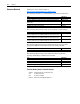
Summary of Changes The information below summarizes the changes to this manual since the last release (July 2005): Description of Changes In Table 1.A, changed column heading from “Output Current at 2 kHz (Amps)” to “Output Current at 4 kHz (Amps).” Changed the last sentence in footnote 2 from “…also capable of running at 3 kHz or 4 kHz…” to “…also capable of running at 2 kHz or 3 kHz.” Changed Table 3.A columns and information. Deleted Table 3.
soc-ii Summary of Changes
Table of Contents Preface Overview Who Should Use this Manual? . . . . . . . . . . . . . . . . . . . . . . . . . . . . . . . . . . . . . . . . . . . . . What Is Not in this Manual . . . . . . . . . . . . . . . . . . . . . . . . . . . . . . . . . . . . . . . . . . . . . . . . Reference Materials . . . . . . . . . . . . . . . . . . . . . . . . . . . . . . . . . . . . . . . . . . . . . . . . . . . . . Manual Conventions . . . . . . . . . . . . . . . . . . . . . . . . . . . . . . . . . . . . . . . . . . . . .
ii Table of Contents Appendix B HIM Overview Remote HIM Connection. . . . . . . . . . . . . . . . . . . . . . . . . . . . . . . . . . . . . . . . . . . . . . . . . . LCD Display Elements . . . . . . . . . . . . . . . . . . . . . . . . . . . . . . . . . . . . . . . . . . . . . . . . . . . ALT Functions . . . . . . . . . . . . . . . . . . . . . . . . . . . . . . . . . . . . . . . . . . . . . . . . . . . . . . . . . . Menu Structure . . . . . . . . . . . . . . . . . . . . . . . . . . . . . . . . . . . . . .
Preface Overview The purpose of this manual is to provide you with the basic information needed to install and troubleshoot the LPM20 Liquid-Cooled AC Drive with High Performance Drive Control. For information on ... Who Should Use this Manual? What Is Not in this Manual Reference Materials Manual Conventions General Precautions Catalog Number Explanation See page ... P-1 P-1 P-2 P-3 P-4 P-5 Who Should Use this Manual? This manual is intended for qualified personnel.
P-2 Overview Reference Materials Publications can be obtained online at http://www.rockwellautomation.com/literature.
Overview Manual Conventions P-3 • In this manual we refer to the LPM20 Liquid-Cooled AC Drive as; drive, LPM20 or LPM20 Drive. • To help differentiate parameter names and LCD display text from other text, the following conventions will be used: – Parameter Names will appear in [brackets]. For example: [DC Bus Voltage]. – Display Text will appear in “quotes.” For example: “Enabled.
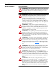
P-4 Overview General Precautions Class 1 LED Product ! ! ! ! ! ! ! ! ATTENTION: Risk of permanent eye damage exists when using optical transmission equipment. This product emits intense light and invisible radiation. Do not look into module ports or fiber optic cable connectors. ATTENTION: This drive contains ESD (Electrostatic Discharge) sensitive parts and assemblies. Static control precautions are required when installing, testing, servicing or repairing this assembly.
4 D 5 Version None 608 A Cat. Code N D608 Cat. Code 500 N E 10 Yes No EMC No Common Mode No Cat. Code N INPUT FILTER ITEMS Q E N N 11 4 3 R C Q S E RIO ControlNet (Coax) ControlNet (Fiber) RS485 DF-1 Ethernet N/A N/A N/A N/A N/A N/A N/A N/A N/A N/A N/A ControlNet (Coax) ControlNet Redundant (Coax) ControlNet (Fiber) ControlNet Redundant (Fiber) DeviceNet EtherNet/IP (Twisted Pair) Requires 700S Phase II Control with Logix Expansion. Note that selections are mutually exclusive.
P-6 Notes: Overview
Chapter 1 Installation/Wiring This chapter provides information on mounting and wiring the LPM20 Drive. For information on ...
1-2 Installation/Wiring Enclosure Ratings LPM20 drives have the following enclosure rating: • Open-Chassis Style: Intended to be installed in an enclosure. LPM20 drives must be placed in an enclosure. Drive Component Locations LPM20 Liquid-Cooled AC drives with High Performance Drive Control are comprised of an input components section and a power module section. Drive Input Component Locations The input components section contains the following main components.
Installation/Wiring 1-3 Figure 1.
1-4 Installation/Wiring Power Module Component Locations The power module section contains the following main components. The numbered items listed below correspond to the numbers used in Figure 1.2 and Figure 1.3. Replacement parts are listed in Chapter 3. 1. 2. 3. 4. 5. 6. 7. 8. 9. 10. 11. 12. 13. 14. 15. 16. 17. 18. 19. 20. 21. 22. 23. 24. 25. 26. 27. 28. 29. 30. 31. Cable Assembly, 40-pin, 0.050 in. Pitch, Flex Film (1) Cable Assembly, 30-pin, 0.050 in. Pitch, Flex Film (1) Cable Assembly, 40-pin, 0.
Installation/Wiring Figure 1.
1-6 Installation/Wiring Figure 1.
Installation/Wiring 1-7 DPI Communication Port The Communication Interface PCB contains an eight-position, female, locking mini-DIN connector that is used as a DPI communication port. This port (DPI Port 4 shown in Figure 1.4 below) provides communication between the LPM20 drive and another DPI device (for example, a HIM). Figure 1.4 DPI Communication Interface Board DPI Port 3 DPI Port 4 DPI Port 5 For more information regarding operating LPM20 drives with a HIM, refer to Appendix B.
1-8 Installation/Wiring Figure 1.5 Power Module Dimensions and Mounting 21.97 Ø.213 Thru For M6 TAPTITE Screw with Enclosure Mounting Bracket 4.75 1.19 1.25 3.05 16.00 1.92 0.80 0.88 1.50 Lifting Ø1.00 Both Sides W 0.75 Drive Output Wiring to Motor 4.48 Ø.472 V Input and Output Wiring Connection SCALE 1:2 U 0.25 DETAIL A 20.66 Coolant Connections See Notes 2 and 3 L3 4.76 13.72 OUT 36.04 A1-P1 Input Filter Harness Connector L2 IN Drive Input 4.48 Wiring 4.48 L1 8.96 9.03 6.
Installation/Wiring DC Neg (-) 4.12 8.27 (A33) 6.17 (A22-TB1 & TB2) 5.54 (DC Bus Measurement Points) 2.92 DC Pos (+) DC Bus Measurement Points on Laminated Bus Ass'y 0.25" x 0.032" Male Faston. Accessible by Removal of Top Cover. 1.15 SCALE SEE DETAIL GATE KILL A22-TB1 & TB2 Main Control Ass'y Terminal Blocks A31 5:16 25.90 A12-P1 Active Converter Control Ass'y Terminal Block 15-Pos. A33 Gate Kill 2-Pos. Terminal Block With #6-32 Phillips/Slotted Screws.
1-10 Installation/Wiring Figure 1.6 Drive Input Dimensions 6.076 Area for Input Power Wiring [154,3] 20.157 [512] Area for Input Power Wiring 23.80 Left Panel/Divider Panel [605] 10.49 [266] 2.38 [60] 26.20 [665] 23.82 [605] Field Install Roof Spacers Rittal p/n DK7967.000 Exhaust Air Space Required C/B Disconnect Handle Divider Panel Rittal p/n TS8609.060 81.11 [2060] 80.89 [2055] 78.99 [2006] 58.
Installation/Wiring 1-11 Verifying Power Module Input Ratings Match Supplied Power It is important to verify that plant power will meet the input power requirements of the LPM20 drive’s Power Module circuitry. See Table 1.A for input power rating specifications. Be sure input power to the drive corresponds to the drive nameplate voltage and frequency.
1-12 Installation/Wiring condition. As a result of this fault, the active converter is also turned off, but this is done via software operation. The firing of IGBTs in the active converter can be disabled independently of any software control by opening the connection between terminals 13 and 14 on the active converter control assembly terminal block A12-P1. This action also genrates a fault in the inverter to enunciate this condition. Wiring diagrams are shown in Figure 1.5 and on page C-3.
Installation/Wiring 1-13 Verifying the Drive’s Watts Loss Rating When mounting the drive inside of an enclosure, you should determine the watts loss rating of the drive from Table 1.A. This table lists the typical full load power loss watts value at 2 kHz (rated carrier frequency). Ensure that the enclosure is adequately ventilated with 0° to 40° C ambient air based on the drive’s watts loss rating.
1-14 Installation/Wiring 2. Run a suitable equipment grounding conductor unbroken from the drive to the motor’s ground terminal and then to earth ground. Use one of the bolts that pass through the drive baseplate and are used to fasten the drive to the wall or cabinet. See Figure 1.6. Tighten these grounding connections to the proper torque as shown in Table 1.D. 3. Connect a suitable grounding conductor to the motor frame and the remote control station (if used).
Installation/Wiring 1-15 Other recommendations include: 1. The allowable coolant temperature range is 0°C to 40°C (32°F to 105°F). When using coolant at a temperature below the dew point of the surrounding air, condensation could accumulate on the drive heatsink and/or circuit boards and damage the drive. In this situation, install a coolant flow regulating device and tube/hose insulation.
1-16 Installation/Wiring Table 1.C Coolant Requirements for LPM20 Drives LPM20 Drive Catalog Number (positions 1-7 only) 20ND608 Coolant Max. Output Temperature Current (Amps) Range (°C) 608 5 to 40 608 0 to 40 550 0 to 40 608 0 to 40 608 0 to 30 Minimum Coolant Flowrate (GPM) 7 7 7 10 7 Pressure Drop From Drive Inlet to Drive Outlet (PSIG) at Minimum Coolant Flow Rate 10 10 10 22 10 (1) Water equals good quality or distilled water with Chemtool, Inc. corrosion inhibitor, 2% inhibitor by volume.
Installation/Wiring Installing Input Power Wiring 1-17 This section describes incoming line components and how to install them. Installing Transformers and Reactors (Not Recommended) The LPM20 AC drive may be used on distribution systems with 100,000 amps or less symmetrical fault current capacity. The Drive Input components consists of a 3% line reactor and a harmonic line filter. Additional input inductance is not recommended. Figure 1.
1-18 Installation/Wiring Installing a Required External/Separate Input Disconnect An input disconnect must be installed in the line before the drive input terminals in accordance with local, national, and international codes (e.g., NEC/CEC). The disconnect should be sized according to the in-rush current as well as any additional loads the disconnect might supply.
Installation/Wiring Installing Output Power Wiring 1-19 This section provides instructions on wiring output contactors, motor overload protection, and output wiring to the motor. Installing Mechanical Motor Overload Protection (Optional) To provide the motor with overload protection, local, national, and international codes (e.g., NEC/CEC) may require one of the following: • a motor thermostat be installed internal to the motor.
1-20 Installation/Wiring Power Wiring ! ATTENTION: National Codes and standards (NEC, VDE, BSI etc.) and local codes outline provisions for safely installing electrical equipment. Installation must comply with specifications regarding wire types, conductor sizes, branch circuit protection, and disconnect devices. Failure to do so may result in personal injury and/or equipment damage. Cable Types Acceptable for 200-600 Volt Installations A variety of cable types are acceptable for drive installations.
Installation/Wiring 1-21 networks. Refer to Reflected Wave in Wiring and Grounding Guidelines for PWM AC Drives, publication DRIVES-IN001. Consideration should be given to all of the general specifications dictated by the environment of the installation, including temperature, flexibility, moisture characteristics and chemical resistance. In addition, a braided shield should be included and specified by the cable manufacturer as having coverage of at least 75%.
1-22 Installation/Wiring Using Input/Output Contactors Input Contactor Precautions ! ! ATTENTION: A contactor or other device that routinely disconnects and reapplies the AC line to the drive to start and stop the motor can cause drive hardware damage. The drive is designed to use control input signals that will start and stop the motor. If an input device is used, operation must not exceed one cycle per minute or drive damage will occur.
Installation/Wiring I/O Wiring 1-23 Important points to remember about I/O wiring: • Use Copper wire only. Wire gauge requirements and recommendations are based on 75°C. Do not reduce wire gauge when using higher temperature wire. • Wire with an insulation rating of 600V or greater is recommended. • Control and signal wires should be separated from power wires by at least 0.3 meters (1 foot). • 4100CCF3 Flex I/O cable for use with DriveLogix™ is 0.9 meters (3 ft.) maximum length.
1-24 Installation/Wiring Table 1.G Recommended Control Wire for Digital I/O Type Wire Type(s) Unshielded Per US NEC or applicable national — or local code Multi-conductor shielded cable 0.750 mm2 (18AWG), such as Belden 8770(or equivalent) 3 conductor, shielded. Shielded Description Insulation Rating 300V, 60°C (140°F) minimum Wiring the Main Control Board I/O Terminals Terminal blocks TB1 and TB2 contain connection points for all inputs, outputs, and standard encoder connections.
Installation/Wiring 1-25 I/O Terminal Blocks Table 1.H Main Control Board I/O Terminal Block Specifications Name I/O Blocks (1) Wire Size Range (1) Maximum Minimum Signal and encoder 1.5 mm2 0.14 mm2 power connections (16 AWG) (28 AWG) Description Maximum 0.25 N-m (2.2 lb.-in.) Torque Recommended 0.22 N-m (1.9 lb.-in.) Maximum/minimum that the terminal block will accept - these are not recommendations. Table 1.
1-26 Installation/Wiring Figure 1.
Installation/Wiring 1-27 Figure 1.10 TB1 Terminals — Analog Wiring Examples (Continued) Input/Output Connection Example Analog Output +/- 10V dc 0-10V Analog Output Used to drive analog meters displaying speed and current. Required Parameter Changes Using Analog Output 1 (-10V to +10V) to meter Motor RPM and direction: 1 2 • Send the data to the Analog Output Parameter 833 [Anlg Out1 Real], the destination, linked to Parameter 71 [Filtered SpdFdbk], the source.
1-28 Installation/Wiring Table 1.
Installation/Wiring 1-29 Figure 1.11 TB2 Terminals — Digital Wiring Examples Input/Output Connection Example Digital Inputs used for enable Sourcing Digital Inputs - using internal power supply and precharge control. Note: 24V dc Supply - supports only on-board digital inputs. Do not use for circuits outside the drive. Note: The factory default for all Digital Inputs is 24V. This must be switched in order to use 115V.
1-30 Installation/Wiring Figure 1.11 TB2 Terminals — Digital Wiring Examples (Continued) Input/Output Connection Example Digital Inputs - 24V dc Sourcing Digital Inputs - using internal power supply, 2-Wire Control 1 2 Com 3 9 5 10 6 11 7 12 8 13 • Set Parameter 829 [DigIn 5 Sel] to a value of 7 (Run). • Parameter 153 [Control Options] bit 8 (3WireControl) will automatically be OFF for 2-wire control.
Installation/Wiring Main Control Board I/O and Encoder Settings JUMPER P22 4 2 3 1 = HW Enable S1 SWITCH S5 4 2 SIDE VIEW 3 1 = No HW Enable FRONT TOP VIEW Up = Open = Off 1 2 Down = Closed = On SWITCH S2 SIDE VIEW Up = Open = Off FRONT TOP VIEW 1 2 Down = Closed = On 3 4 SWITCH S4 SIDE VIEW SWITCH S3 SIDE VIEW Up = Open = Off Up = Open = Off FRONT TOP VIEW FRONT TOP VIEW 1 2 Down = Closed = On 1 2 Down = Closed = On Table 1.
1-32 Installation/Wiring Connecting SynchLink SynchLink provides high-speed synchronization and communication between multiple LPM20 drives with High Performance Drive Control (or other products with SynchLink capability). Class 1 LED Product ! ATTENTION: Hazard of permanent eye damage exists when using optical transmission equipment. This product emits intense light and invisible radiation. Do not look into module ports or fiber optic cable connectors.
Installation/Wiring 1-33 Table 1.L SynchLink Cables and Accessories (Continued) Description SynchLink Fiber-Hub, 1 input, Base SynchLink Fiber-Hub, 4 output, “Star” Splitter SynchLink Bypass Switch Cat. No. 1751-SLBA 1751-SL4SP 1751-SLBP/A Table 1.
1-34 Installation/Wiring Pre-charge Operation The pre-charge bypass contactor is controlled by the active converter. On power up, the contactor is open so the pre-charge resistors limit the current charging the DC link.
Installation/Wiring 1-35 Figure 1.12 Active Converter Control Board I/O Terminal Locations A12 - Active Converter Control Assembly SW1 DPI Slave = OFF (Default) ON DPI Master = ON ON A12 - P1 Terminals SW1 1 2 3 4 5 6 7 8 9 10 11 12 13 14 15 7 6 5 4 3 2 1 A11 - P2 Terminals A11 - Voltage Feedback Resistor Assembly I/O Terminal Blocks Table 1.
1-36 Installation/Wiring Table 1.P Active Converter Voltage Feedback Board A11-P2 Terminal Descriptions Pin 1 4 7 CE Conformity Description L1 L2 L3 EMC Instructions CE Compliance Compliance with the Low Voltage Directive 73/23/EEC and Electromagnetic Compatibility Directive 89/336/EEC has been demonstrated using harmonized European Norm (EN) standards published in the Official Journal of the European Communities.
Installation/Wiring 1-37 Essential Requirements for CE Compliance Conditions 1-5 listed below must be satisfied for LPM20 drives to meet the requirements of EN61800-3: 1. Standard LPM20 CE compliant drive. 2. Grounding as described in Grounding the Drive on page 1-13. 3. Output power wiring to the motor, and all control/signal wiring must use braided shielded cable with a shield coverage of 75% or greater, or metal conduit. 4.
1-38 Notes: Installation/Wiring
Chapter 2 Start Up This chapter describes how to start up the LPM20. Refer to Appendix B for a brief description of the LCD HIM (Human Interface Module). For information on ... Prepare For Drive Start-Up Status Indicators Assisted Start Up ! Prepare For Drive Start-Up See page ... 2-1 2-3 2-4 ATTENTION: Power must be applied to the drive to perform the following start-up procedure. Some of the voltages present are at incoming line potential.
2-2 Start Up Applying Power to the Drive ❏ 6. Apply AC power and control voltages to the drive. If any digital input is configured to “Stop – CF” (CF = Clear Fault) or “Enable,” verify that signals are present or the drive will not start. For a list of potential digital input conflicts or if a fault code appears, please refer to the PowerFlex 700S High Performance AC Drive — Phase II Control User Manual (Publication No. 20D-UM006…), Chapter 4. ❏ 7.
Start Up Status Indicators Figure 2.
2-4 Start Up Figure 2.2 Drive RUN LED on PF700S Control Cassette Drive RUN LED RUN I/O DriveLogix Indicators FORCE (only supplied when drive is equipped with DriveLogix™5730 Controller) COM BAT OK Name Color Drive RUN LED Green (topmost indicator) DriveLogix Indicators State Description Off Drive inverter is not providing a modulated output. Steady Drive inverter is providing a modulated output.
Chapter 3 Troubleshooting Chapter 3 provides information to guide you in troubleshooting the LPM20 with High Performance Drive Control. For information on ... Faults and Alarms Drive Status Manually Clearing Drive Faults Drive Fault Descriptions Active Converter Fault Descriptions Clearing Drive Alarms Common Symptoms and Corrective Actions Test Equipment Needed To Troubleshoot Verifying That DC Bus Capacitors Are Discharged Replacement Parts Faults and Alarms See page ...
3-2 Troubleshooting Drive Status Power Module LED Indications The Inverter Status LED and Rectifier Status LED are located on the DPI Communications Interface Board on the front of the power module. The LEDs indicate the status of the inverter and the rectifier as shown in the table in Figure 3.1. Note that if the LEDs are off, it indicates the drive is not receiving power. Figure 3.
Troubleshooting 3-3 HIM Indication The LCD HIM also provides visual notification of a fault or alarm condition. Condition Drive is indicating a fault. The LCD HIM immediately reports the fault condition by displaying the following: • • • • “Faulted” appears in the status line Fault number Fault name Time that has passed since fault occurred Press Esc to regain HIM control. Drive is indicating an alarm.
3-4 Troubleshooting Common Symptoms and Corrective Actions Drive does not Start from Start or Run Inputs wired to the terminal block. Cause(s) Drive is faulted. Indication Flashing red status light. Corrective Action Clear the fault: • Press HIM Stop key if HIM is control source. • Cycle power. • Set [Fault Clear] parameter to 1. Incorrect input wiring. See None Figure 1.11 for wiring examples. Incorrect digital input programming. None • Mutually exclusive choices have been made (i.e.
Troubleshooting 3-5 Motor and/or drive will not accelerate to Commanded Speed. Cause(s) Acceleration time is excessive. Excess load or short acceleration times force the drive into current limit, slowing or stopping acceleration. Indication None None Speed command source or value is None not as expected. Programming is preventing the drive None output from exceeding limiting values. Corrective Action Reprogram [Accel Time x] parameter. 1.
3-6 Troubleshooting Test Equipment Needed To Troubleshoot Verifying That DC Bus Capacitors Are Discharged An isolated multimeter will be needed to measure the DC bus voltage and to make resistance checks. Note that dedicated troubleshooting test points are not provided. ! ATTENTION: DC bus capacitors retain hazardous voltages after input power has been disconnected.
Troubleshooting Replacement Parts 3-7 Table 3.A lists the replacement parts that are available from Allen-Bradley. For parts locations, refer to Figure 1.1, Figure 1.2, and Figure 1.3. Table 3.A Drive Replacement Parts Drive Voltage Current Class Rating 400/480 608A 400/480 608A 400/480 608A 400/480 608A 400/480 608A 400/480 608A 400/480 400/480 400/480 400/480 608A 608A 608A 608A Qty.
3-8 Notes: Troubleshooting
Appendix A Supplemental Drive Information For information on ... Specifications Communication Configurations See page ... A-1 A-3 Specifications Category Specification Agency Listed to UL508C and CAN/CSA-C2.2 No. 14-M91.
A-2 Supplemental Drive Information Category Specification Environment Atmosphere: (continued) Electrical Relative Humidity: Shock: Vibration: Voltage Tolerance: Frequency Tolerance: Input Phases: Control Displacement Power Factor: Efficiency: Max.
Supplemental Drive Information Category Feedback Specification Encoder Inputs (2): Encoder Voltage Supply: Maximum Input Frequency: Stegmann Hi-Resolution Option: A-3 Dual Channel Plus Marker, Isolated with differential transmitter output (Line Drive), Incremental, Dual Channel Quadrature type 5V dc or 12V dc (5V dc requires an external power supply), 320 mA/channel 400 kHz Encoder Voltage Supply: 11.5V dc @ 130 mA Hi-Resolution Feedback: Sine/Cosine 1V P-P Offset 2.
A-4 Supplemental Drive Information Logic Command Word Logic Bits 15 14 13 12 11 10 9 8 7 6 5 4 3 2 1 0 Command Description x Normal 0 = Not Normal Stop Stop 1 = Normal Stop 0 = Not Start x Start (1) 1 = Start x Jog 1 0 = Not Jog using [Jog Speed 1] 1 = Jog using [Jog Speed 1] 0 = Not Clear Fault x Clear 1 = Clear Fault Fault(2) x x Unipolar 00 = No Command Direction 01 = Forward Command 10 = Reverse Command 11 = Hold Direction Control x Reserved x Jog 2 0 = Not Jog using [Jog Speed 2] 1 = Jog using [Jog S
Supplemental Drive Information A-5 Logic Status Word Logic Bits 15 14 13 12 11 10 9 8 7 6 5 4 3 2 1 0 Status x Enabled x x x x x x x x x x x x x x x (1) Description 0 = Not Enabled 1 = Enabled Running 0 = Not Running 1 = Running Command 0 = Reverse Direction 1 = Forward Actual 0 = Reverse Direction 1 = Forward Accel 0 = Not Accelerating 1 = Accelerating Decel 0 = Not Decelerating 1 = Decelerating Jogging 0 = Not Jogging 1 = Jogging Fault 0 = No Fault 1 = Fault Alarm 0 = No Alarm 1 = Alarm Flash Mode 0 =
A-6 Notes: Supplemental Drive Information
Appendix B HIM Overview For information on … Remote HIM Connection LCD Display Elements ALT Functions Menu Structure Viewing and Editing Parameters Removing/Installing the HIM Remote HIM Connection See page B-1 B-2 B-2 B-3 B-5 B-6 The LPM20 provides a cable connection point (DPI Port 4) for a remote LCD HIM. This port is located on the Communications Interface Assembly (item 29 shown in Figure 1.3). Figure B.
B-2 HIM Overview LCD Display Elements Display Description F-> Power Loss Direction | Drive Status | Alarm | Auto/Man | Information Commanded or Output Frequency Auto 0.0 Hz Main Menu: Diagnostics Parameter Device Select ALT Functions Programming / Monitoring / Troubleshooting To use an ALT function, press the ALT key, release it, then press the programming key associated with one of the following functions: Table B.A ALT Key Functions ALT Key and then … S.M.A.R.T.
HIM Overview Menu Structure B-3 Figure B.
B-4 HIM Overview Parameter Menu Refer to Viewing and Editing Parameters on page B-5. Device Select Menu Use this menu to access parameters in connected peripheral devices. Memory Storage Menu Drive data can be saved to, or recalled from, User and HIM sets. User sets are files stored in permanent non-volatile drive memory. HIM sets are files stored in permanent non-volatile HIM memory.
HIM Overview Viewing and Editing Parameters B-5 LCD HIM Step 1. In the Main Menu, press the Up Arrow or Down Arrow to scroll to “Parameter.” Key(s) Example Displays or FGP: File Monitor Motor Control Dynamic Control 2. Press Enter. “FGP File” appears on the top line and the first three files appear below it. 3. Press the Up Arrow or Down Arrow to scroll through the files. or 4. Press Enter to select a file. The groups in the file are displayed under it.
B-6 HIM Overview Removing/Installing the HIM The HIM can be removed or installed while the drive is powered. Important: HIM removal is only permissible in Auto mode. If the HIM is removed while in Manual mode or the HIM is the only remaining control device, a fault will occur. Step To remove the HIM … 1. Press ALT and then Enter (Remove). The Remove HIM confirmation screen appears. 2. Press Enter to confirm that you want to remove the HIM. 3. Disconnect the HIM from the drive. To install HIM … 1.
Appendix Wiring Diagrams Wiring diagrams on the following pages illustrate the drive and power module wiring. For information on ... Drive Power Module – Overall Power Module – Active Converter Control and Rectifier Power Interface Power Module – High Voltage Interconnect and Inverter Power Interface Power Module – Rectifier IGBT and Inverter IGBT See page ...
C-2 Wiring Diagrams Drive T1 Control Transformer (3kVA, 120V, 25A) 15A/600V Class 'RK-5' 1 2 H1 FU1 FU2 H* AC INPUT L1 CB1 Main Circuit Breaker L2 L3 Class 'CC' 600VAC Time Delay 1 25A 2 5A FU13 X1 FU3 X2 *T1 Input (50/60Hz) H1-H4: 380-415VAC H1-H5: 440-480VAC 2 1 Shunt Trip ST R S T Class 'CC' 1A/600V Time Delay 1 2 FU7 FU8 FU9 1 2 3 Fan 1 M2 2 150A 1 500V 2 FU6 6 IND1 Input Inductor 5 1 2 FU4 4x, MOV 140J 2 M3 1 Fan TS1 7 8 1 20A FU10 600V 2 Precharge R4 Resistors 10Ω, 600W
Wiring Diagrams FUSE TABLE - DRIVE INPUT Ref.
C-4 Wiring Diagrams Power Module – Overall INPUT FILTER CONNECTIONS EXTERNAL DPI 180807-C01 - 7 Pos. Plug L1 P2 VOLTAGE F/B RESISTOR ASSY. L3 J8 180675-A03 POWER & CONTROL A12 CHILLPLATE TEMP. SENSOR A1-P1 179828-Q01 179710 J14 J9 J5 J3 A13 J4 J1 179753 J3 179754 J2 INPUT FILTER CONNECTIONS J7 J6 J13 J1 194706-Q01 J2 JP1 J2 RECTIFIER POWER INTERFACE ASSY. See Table on Page C-11 J7 179571 SEE DETAIL A J5 DP1 3 COMMUNICATION INTERFACE ASSY.
Wiring Diagrams C-5 I/O & CONTROL TB1 700S CONTROL & FEEDBACK OPTIONS; AND ADD'L CONFIGURATIONS TB2 From A24-J2 J6 179828-Q02 J4 P6 DC BUS, U, V, & W J1 28-Pin Board-To-Board J3 P3 A36 A35 HIGH VOLTAGE INTERCONNECT ASSY. MOTOR VOLTAGE FEEDBACK ASSY.
C-6 Wiring Diagrams Power Module – Active Converter Control and Rectifier Power Interface J2 To A22-P2 See Pages C-8/C-9 +5V INV +5V INV +5V INV +5V INV +5V INV +5V INV +12V INV +12V INV +12V INV DGND DGND DGND DGND DGND DGND DGND CAN HI CAN LO DGND DGND COMM RXD INV COMM TXD INV COMM CS INV COMM CLK INV LED RED INV LED GRN INV +24V INV 24VCOM INV 30 29 28 27 26 25 24 23 22 21 20 19 18 17 16 15 14 13 12 11 10 9 8 7 6 5 4 3 2 1 A31 COMMUNICATION INTERFACE ASSY.
Wiring Diagrams J1 POWER LAYER INTERFACE J6 J5 2 1 4 3 6 5 8 7 10 9 12 11 14 13 16 15 18 17 20 19 22 21 24 23 26 25 28 27 30 29 32 31 34 33 36 35 38 37 40 39 1 2 3 4 5 6 7 8 9 10 11 12 13 14 15 16 17 18 19 20 21 22 23 24 25 26 27 28 29 30 31 32 33 34 35 36 37 38 39 40 24VCOM ISO +24V ISO +5V PS +5V PS +5V PS +5V PS GND PS GND PS GND PS GND PS +12V +12V GND PS -12V EE+5VDC GND PS EE SK EE IO EE GND EE CS GNDSHRT /CHARGE U NEG+ U POS+ V NEG+ V POS+ W NEG+ W POS+ NTC+ /GATE KILL RESET U AMPS+ GND PS VV A
C-8 Wiring Diagrams Power Module – High Voltage Interconnect and Inverter Power Interface P1 TB1 See Installation Manual for I/O Wiring 1 2 3 4 5 6 7 8 9 10 11 12 13 14 15 16 17 18 19 20 21 22 23 24 POWER LAYER INTERFACE CUSTOMER I/O A22 MAIN CONTROL ASSY.
Wiring Diagrams J5 1 2 3 4 5 6 7 8 9 10 11 12 13 14 15 16 17 18 19 20 21 22 23 24 25 26 27 28 29 30 31 32 33 34 35 36 37 38 39 40 J6 GATE DRIVER INTERFACE MAIN CONTROL INTERFACE 1 2 3 4 5 6 7 8 9 10 11 12 INVERTER U+COLLECTOR TO INVERTER IGBT ASSY. #1-J2 INVERTER U+GATE INVERTER U+EMITTER INVERTER V+COLLECTOR TO INVERTER IGBT ASSY. #2-J3 INVERTER V+GATE INVERTER V+EMITTER J7 GATE DRIVER INTERFACE A23 INVERTER POWER INTERFACE ASSY.
C-10 Wiring Diagrams Power Module – Rectifier IGBT and Inverter IGBT RECTIFIER IGBT ASSY #1 RECTIFIER IGBT ASSY #2 A16 See Table on Page C-11 See Table on Page C-11 J2 J1 1 2 3 4 5 6 7 8 9 10 1 2 3 4 5 6 7 8 9 10 11 12 13 14 1 2 3 4 5 6 7 8 9 10 11 12 13 14 1 2 3 4 5 6 7 8 9 10 2 G C 4 RECTIFIER L2+COLLECTOR RECTIFIER L2+GATE RECTIFIER L2+EMITTER RECTIFIER L2-COLLECTOR See Pages C-6/C-7 RECTIFIER L2-GATE RECTIFIER L2-EMITTER See Pages See Pages C-6/C-7 C-8/C-9 RECTIFIER L1+COLLECTOR RECTI
Wiring Diagrams A25 INVERTER IGBT ASSY #1 A26 See Table on this page INVERTER IGBT ASSY #2 See Table on this page J2 J1 1 2 3 4 5 6 7 8 9 10 1 2 3 4 5 6 7 8 9 10 11 12 13 14 INVERTER W+COLLECTOR INVERTER W+GATE INVERTER W+EMITTER INVERTER W-COLLECTOR INVERTER W-GATE INVERTER W-EMITTER See Pages C-8/C-9 INVERTER NTC2+ INVERTER NTC2- J3 J1 1 2 3 4 5 6 7 8 9 10 11 12 13 14 1 2 3 4 5 6 7 8 9 10 INVERTER V+COLLECTOR INVERTER V+GATE INVERTER V+EMITTER INVERTER V-COLLECTOR INVERTER V-GATE INVERTER
C-12 Notes: Wiring Diagrams
Index A AC input ground, 1-13 wiring, 1-17 AC supply, unbalanced or ungrounded, 1-11 active converter assembly fault descriptions, 3-3 agency certification, A-1 biocide treatment, 1-16 connections to drive, 1-15 considerations, 1-14 corrosion inhibitor, 1-16 requirements, 1-15 Copycat, B-4 D air flow clearance requirements, 1-10 data saving, B-4 alarm clearing, 3-3 types, 3-1 diagnostic data, viewing, B-3 ALT key functions, B-2 Dowtherm, 1-16 armored cable, 1-20 DPI communication port, 1-7, B-1 d
Index-2 H HIM Device User Sets, B-4 diagnostics, B-3 memory storage, B-4 menu structure, B-3 preferences, setting, B-4 removing/installing, B-6 Reset to Defaults, B-4 I I/O wiring, 1-23 TB1 Terminal examples, 1-26 TB2 Terminal examples, 1-29 P parameter changing/editing, B-5 viewing, B-5 port, DPI type, B-1 power before applying, 2-1 cables/wiring, 1-20 conditioning, input, 1-11 loss watts rating, 1-13 ratings for drive, 1-1 wiring, installing, 1-18 powering up the drive, 2-1 precautions, general, P-4 i
Index-3 TB2 Terminals, 1-28 terminal block wire size encoder - Main Control Board, 1-25 I/O - Active Converter Control Board, 1-35 I/O - Main Control Board, 1-25 transformers and reactors, installing, 1-17 troubleshooting, 3-1 U unbalanced/ungrounded supply, 1-11 unshielded power cables, 1-20 user configurable alarm, 3-1 V viewing and changing parameters, B-5 W web site ControlNet installation references, P-2 drive reference materials, P-2 DriveLogix5730 Controller, P-2 feedback devices, P-2 SynchLink D
Index-4
U.S. Allen-Bradley Drives Technical Support - Tel: (1) 262.512.8176, Fax: (1) 262.512.2222, Email: support@drives.ra.rockwell.com, Online: www.ab.com/support/abdrives www.rockwellautomation.com Power, Control and Information Solutions Headquarters Americas: Rockwell Automation, 1201 South Second Street, Milwaukee, WI 53204-2496 USA,Tel: (1) 414.382.2000, Fax: (1) 414.382.