
User Manual
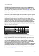


Limit temperatures (°C)
Insulation class E B F H
„d“, Continuous service 115 120 145 165
„e“, Continuous service 105 110 130 155
„e“, at the end of the t
E
-time 175 185 210 235
Tab. 2.4-5
Limit temperatures of motors of ignition protection type “e” and “d” in relation to the insulation material
class of the windings
With respect to the temperature rise characteristics of an electrical machine, two operating
statuses should be taken into account: continuous duty and stalled rotor motor.
At continuous duty under full load the machine slowly heats up and after several hours,
depending on its size, re
aches its steady-state temperature. At the highest permissible ambient
temperature, this steady-state temperature may not exceed the limit temperature of the
insulation material class nor of the temperature class.
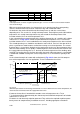
In the schematically presented example of the heating characteristics of a machine of insulation
ma
terial class F in Fig. 2.4-15, neither the permitted limit of temperature class T4 nor that of
insulation material class F are exceeded once the steady-state temperature has bee
n reached.
The second operating case should be considered as more critical. It occurs if the rotor of the 3-
phase asynchronous motor becomes stalled aft
er running at service temperature. The current
that then flows is several times higher than the rated current and causes the temperature of the
rotor and stator windings to rise rapidly. A monitoring device must disconnect the machine from
the supply within the heating time t
E
, i.e. the time for the limit temperature of the windings to be
reached. The heating time t
E
is the time after which the permissible temperature is reached with
a stalled rotor condition starting from service temperature. It is a characteristic quantity of the
motor.
As the selected example of a motor with stalled rotor in Fig. 2.4-15 shows, the limit tempera-
tures of the temperature class f
or applications T4 and T3 determine the t
E
-time.
0
50
100
150
200
250
300
0 140
Continuous operation (t / h) Locked rotor (t / s)
t
°C
0
T2=300°C
Iso.-Cl.
F
=210°C
(short-time)
T4=135°C
Iso.-Cl.
F
=130°C
(permanently)
T3=200°C
t
E
(T4)
t
E
(T3)
t
E
(T2)
Iso.-Kl. F =
195°C
(Limit temparature at T3)
Fig. 2.4-15
Schematic presentation of the heating characteristic of a motor. When locked at service temperature, the
motor must be disconnected from the supply within the t
E
time.
If however the machine is intended for hazardous areas of temperature class T2 (or
T 1), the thermal limit is determined by the short-term permissible limit temperature of isolation
material class F of 210 °C.
Ex-motors are not inherently explosion protected. They achieve the required explosion protec-
tion by means of complementary in
stallation measures, including appropriate selection of
LVSAM-WP001A-EN-P - April 2009
2-44