
User Manual
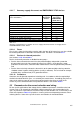
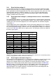

2.2.1.7 Summary supply disconnect and EMERGENCY STOP devices
Requirements on supply disconnect devices
(under IEC 6
0204-1)
Supply
disconnect
devices
Supply
disconnect/
EMERGENCY
STOP devices
Operator handle:
- Black or gray handle yes no
- Red handle with yellow background no yes
- Lockable yes yes
Manual actuation from outside yes yes
Easily accessible yes yes
Only one “ON” and “OFF” position yes yes
Position indicator only “О” and “I” yes yes
Lockable in “О” position from outside yes yes
Touch-protected input terminals with warning symbol yes yes
Tab. 2.2-1
Summary of requirements on switches for use as supply disconnect devices and supply discon-
nect/EMERGENCY STOP devices
2.2.1.8 Fuses
Fuses have a short-circuit breaking capacity and in the form of full-range fuses are also suitable
for overload protection of conductors and certain loads. For details see Section 4.2.1.
2.2.1.9 Devices for thermal protection
See Sections 4.1.2, 4.2 and 4.2.4.
Devices for thermal protection are divided into two groups:
Devices that evaluate the thermal risk to the protected object and provide a protective
disconne
ction in one unit (for example full-range fuses, MCB’s, circuit breakers, motor-
protection circuit breakers, electronic motor control devices with integrated motor protection)
and
Devices that exclusively evaluate the thermal risk to the protected object but for protective
shutdown control a power switching
device (usually a contactor). These include for example
overload relays and thermistor (PTC) protection devices.
2.2.1.10 Contactors
Contactors are designed for operational switching and - in accordance with the required high
mechanical and electrical life span - use relatively low contact forces. Accordingly they have no
short-circuit switching capacity and must be protected against the effects of short-circuit
currents by series-connected short-circuit protective devices. See Section
2.3.4.5.
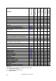
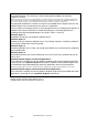
2.3 Parameters for the correct selection and sizing
For the specific application of low-voltage devices additional parameters should be taken into
account such as for example the application ambient temperature, the expected device life
span, any influences from moisture, mechanical impacts and vibrations etc., to name only a few
of the most important. Tab. 2.3-1 provides a summary of the most important parameters when
selecting devices. Some of the specific features
are looked at in more detail below.
LVSAM-WP001A-EN-P - April 2009
2-5