
User Manual
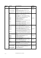
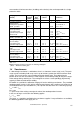

supplies, see Tab. 1.7-1.
Pole
number
2 4 6 8 10 12 16 24 32 48
n
s 50 Hz
3000 1500 1000 750 600 500 375 250 188 125
n
s 60 Hz
3600 1800 1200 900 720 600 450 300 225 150
Tab. 1.7-1
Synchronous speeds for 50 and 60 Hz power supplies
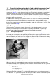
The rotating field of the stator induces a voltage in the coil of the rotor, which in turn creates a
current flow therein. With the interaction of the rotating field of the stator with the conductors in
the rotor through which a current flows, a torque is created in the direction of the rotating field.
The speed of the rotor is always smaller than the synchronous speed by the so-called slip s.
s = (n
s
-n)/n
s
s slip
n
s
synchronous speed
n operational speed
It is only because of this speed differential that a voltage can be induced in the rotor and hence
the rotor curr
ent that is the prerequisite for the generation of the motor-torque. The slip in-
creases with the load torque. Its rated value at the rated load of the motor depends on the rotor
resistance and hence on the energy efficiency of the motor.
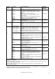
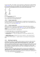
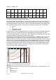
The torque curve of the induction motor is characterized by the breakdown-torque. This means
that the torque of the motor increase
s with increasing speed to a maximum value and then
rapidly falls back to zero at the synchronous speed. If the mechanical load of a motor running at
normal service is increased beyond the value of the breakdown torque, it will stall, i.e. it comes
to a halt. The magnitude of the breakdown torque is determined by the electrical reactance of
the motor and hence by the motor’s design. The slip that occurs at breakdown torque can be
influenced by the rotor resistance. This effect is exploited in slip-ring motors by switching on
external resistors (
Fig. 1.7-2 and Fig. 1.7-3).
s
T
R
2
2*R
2
3*R
2
10
T
b
s
b
3
s
b
2
s
b
1
Fig. 1.7-2
The torque characteristic of asynchronous motors can quasi be extended by connecting resistors in the
rotor circuit.
T
b
breakdown torque
s slip
s
b
breakdown slip
R
2
rotor resistance
LVSAM-WP001A-EN-P - April 2009
1-10