
User Manual
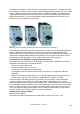
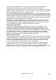
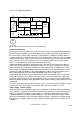

Tripping with three-pole load
Tripping with two-pole load, the middle bimetal strip being unheated
1 = Bimetal strip
2 =
Phase failure slide
3 = Overload slide
4 = Differential lever
5 = Contact lever
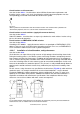
S
1
= Tripping movement at overload
S
2
= Tripping movement with phase failure
S
3
= Opening the trip contact
Fig. 4.2-11
Principle of operation of
the differential release for thermal motor protection relays
For this purpose, motor protection relays have a double slide arrangement in the form of a
phase failure slide and
an overload slide. In the case of phase failure, the de-energized, cooling-
down bimetal strip moves the phase-failure slide in the opposite direction to the overload slide.
Via a differential lever, this countermovement is converted into an additional tripping displace-
ment (
Fig. 4.2-11).
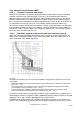
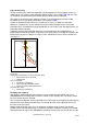
In the event of phase failure, this double slide device causes tripping at a lower current than with
a 3-phase load (characte
ristic curve b in Fig. 4.2-13).
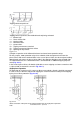
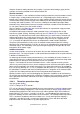
Single-phase operation
For protection of single
phase AC current- or direct current loads, all poles should be connected
in series to ensure the force required for tripping the switch mechanism and to prevent tripping
by the phase failure protection (
Fig. 4.2-12).
Fig. 4.2-12
Series connection of the poles of the motor protection relay for single-phase operation
LVSAM-WP001A-EN-P - April 2009
4-38