Quick Start Logix5000 Control Systems: Connect PowerFlex 40 Drives over an EtherNet/IP Network Catalog Numbers Logix5000 Controllers, PowerFlex 40 Drives
Important User Information Solid-state equipment has operational characteristics differing from those of electromechanical equipment. Safety Guidelines for the Application, Installation and Maintenance of Solid State Controls (publication SGI-1.1 available from your local Rockwell Automation sales office or online at http://www.rockwellautomation.com/literature/) describes some important differences between solid-state equipment and hard-wired electromechanical devices.
Table of Contents Preface About This Publication . . . . . . . . . . . . . . . . . . . . . . . . . . . . . . . . . . . . . . . . . . . . . 5 Before Using This Publication. . . . . . . . . . . . . . . . . . . . . . . . . . . . . . . . . . . . . . 5 Controller and Other Component Quick Starts . . . . . . . . . . . . . . . . . . . . . 8 Before You Begin. . . . . . . . . . . . . . . . . . . . . . . . . . . . . . . . . . . . . . . . . . . . . . . . . . 8 Where to Start . . . . . . . . . . . . . . . . . . . . .
Table of Contents Notes: 4 Rockwell Automation Publication IASIMP-QS029A-EN-P - February 2012
Preface About This Publication This quick start provides examples and procedures for integrating a PowerFlex 40 drive in a Logix5000 control system over an EtherNet/IP network. The programming examples are not complex, and offer easy solutions to verify that devices are functioning and communicating properly. IMPORTANT This publication describes example tasks you can complete when using a PowerFlex 40 drive on an EtherNet/IP network.
Preface Table 1 - Required Tasks to Complete Before Using this Quick Start Task Description Prepare the Logix5000 Assembling the control system and connecting to communication networks. Some components, for example, control system the desired Logix5000 controller and system power supply, are required. Other components, for example, a hardware network communication module, are optional. IMPORTANT: These graphics show the assembly of an example Logix5000 controller.
Preface Table 1 - Required Tasks to Complete Before Using this Quick Start Task Description Configure the networks Complete required tasks associated with the networks used in your application, such as assigning an IP address to the controller or a communication module in your Logix5000 control system.
Preface Controller and Other Component Quick Starts This quick start describes how to use one device on one network in a Logix5000 control system. Typically, though, a Logix5000 control system includes more than the controller and one device on one network. For example, if a Logix5000 control system operates on an EtherNet/IP network, in addition to a controller, power supply, and communication modules, the system might use remote I/O modules, drives, and HMI terminals.
Preface Where to Start Prerequisite Tasks Described in Before Using This Publication on page 5. 1. Prepare the Logix5000 control system hardware 2. Prepare the computer 3. Configure the networks 4.
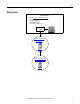
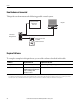
Preface How Hardware is Connected This quick start demonstrates the following possible control system. Logix5000 Controller with Ethernet Connection Stratix 6000 Managed Switch Computer 8 7 6 5 4 3 PowerFlex 40 Drive with 22-COMM-E Communication Card 2 1 Required Software To complete examples in this quick start, you need the software described in this table. Software Required Version Required for This Task RSLogix 5000 20.00.
Preface Parts List You need these parts to complete the tasks described in this quick start. Quantity Cat. No. Description 1 22B-V2P3N104 PowerFlex 40 drive AC drive 1 22-COMM-E Communication adapter for use with the PowerFlex 40 drive 1 1585J-M8PBJM-2 RJ45-to-RJ45 patchcord Ethernet cables For a list of parts required to complete the prerequisite tasks listed in Table 1 - Required Tasks to Complete Before Using this Quick Start on page 6, see the documentation describing those tasks.
Preface Notes: 12 Rockwell Automation Publication IASIMP-QS029A-EN-P - February 2012
Chapter 1 Prepare the PowerFlex 40 Drive Hardware In this chapter, you learn how to complete the following tasks: • Mount and wire power to a 22B-V2P3N104 drive. • Configure EtherNet/IP communication for the drive.
Chapter 1 Prepare the PowerFlex 40 Drive Hardware Follow These Steps Mount the 22BV2P3N104 Drive page 15 Wire Power page 15 R/L1 S/L2 T/L3 U/T1 V/T2 W/T3 DC- DC+ BR+ BR- Connect the EtherNet/IP Adapter to the Drive page 17 Configure the EtherNet/IP Adapter page 19 14 Rockwell Automation Publication IASIMP-QS029A-EN-P - February 2012
Prepare the PowerFlex 40 Drive Hardware Chapter 1 Mount the 22B-V2P3N104 Drive You should mount the drive upright on a flat, vertical, and level surface with considerations for minimum mounting clearance, ambient operating temperature, debris protection, and storage. To complete the tasks described in this chapter, mount the 22B-V2P3N104 drive on a DIN rail. For complete mounting instructions, see the PowerFlex 40 Drives User Manual, publication 22B-UM001.
Chapter 1 Prepare the PowerFlex 40 Drive Hardware 4. Remove the terminal block cover to access the power connections. The drive can use any of the following inputs: • 120V AC single phase • 230V AC single phase • 230V AC three phase • 480V AC three phase R/L1 S/L2 T/L3 U/T1 V/T2 W/T3 In this quick start, you use 120V AC single phase. DC- DC+ BR+ BR- 5. Connect the AC power conductors to the drive terminals as described in the following table and tighten the screws.
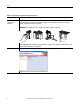
Prepare the PowerFlex 40 Drive Hardware Chapter 1 Connect the EtherNet/IP Adapter to the Drive WARNING: Verify that all incoming power is turned off before connecting the adapter to the drive. 1. Before you connect the adapter to the 22B-V2P3N104 drive, record the Ethernet (MAC ID) address. 22-COMM - E 00:00:BC:08:90:65 22-COMM-E HW Address: 00:00:BC:08:90:65 You need this number to set an IP address for the adapter, as described in Configure the EtherNet/IP Adapter on page 19.
Chapter 1 Prepare the PowerFlex 40 Drive Hardware 5. Install the drive cover onto the drive using both cover fasteners to ground the adapter. 0.5…0.6 Nm (4…5 lbin) 6. Connect the adapter to the EtherNet/IP network via the EtherNet/IP port at the bottom of the drive. 8 7 6 5 4 3 2 1 7. Apply power to the PowerFlex 40 drive.
Prepare the PowerFlex 40 Drive Hardware Chapter 1 Configure the EtherNet/IP Adapter The PowerFlex 40 EtherNet/IP network adapter requires a network IP address to operate on an EtherNet/IP network. Use the BOOTP/DHCP server to assign an IP address. 1. Retrieve the MAC ID you recorded in step 1 on page 17. 2. Start the BOOTP/DHCP utility. 3. From the Tools menu, choose Network Settings. 4. Type the Subnet Mask of the network.
Chapter 1 Prepare the PowerFlex 40 Drive Hardware 7. Click Add to Relation List. The New Entry dialog box appears. 8. Type an IP Address, Hostname, and Description for the adapter. 9. Click OK. 10. To permanently assign this configuration to the adapter, wait for the adapter to appear in the Relation List panel and select it. 11. Click Disable BOOTP/DHCP. When power is cycled, the adapter uses the assigned configuration and does not issue a BOOTP request.
Chapter 2 Add the PowerFlex 40 Drive to an RSLogix 5000 Project In this chapter, you add a 22B-V2P3N104 drive to an RSLogix 5000 project and configure it. You also download the project to the controller so you can verify communication with the drive.
Chapter 2 Add the PowerFlex 40 Drive to an RSLogix 5000 Project Follow These Steps Add the 22B-V2P3N104 Drive to Your RSLogix 5000 Project page 23 Download the Project to Your Logix5000 Controller page 26 Connect to the 22BV2P3N104 Drive page 27 Edit the 22BV2P3N104 Drive Parameters page 29 Test the 22BV2P3N104 Drive Tags page 29 22 Rockwell Automation Publication IASIMP-QS029A-EN-P - February 2012
Add the PowerFlex 40 Drive to an RSLogix 5000 Project Chapter 2 Add the 22B-V2P3N104 Drive to Your RSLogix 5000 Project IMPORTANT The tasks described in this section use an RSLogix 5000 project for a CompactLogix 5370 L3 controller. CompactLogix 5370 L3 controllers require that you use RSLogix 5000 software, version 20.00.00 or later. If your are using a different Logix5000 controller, your project’s RSLogix 5000 software version requirements might be different. 1.
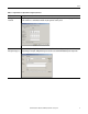
Chapter 2 Add the PowerFlex 40 Drive to an RSLogix 5000 Project 4. Enter a name for the drive. 5. Enter the same IP Address for the 22B-V2P3N104 drive in the project as you assigned in Configure the EtherNet/IP Adapter on page 19. 6. Click Change. 7. On the Module Definition dialog box, disable keying and click Match Drive. 8. On the Full or Partial Match dialog box, click Partial. 9. On the Connect to Drive dialog box, navigate to the drive. 10. Select the drive and click OK.
Add the PowerFlex 40 Drive to an RSLogix 5000 Project Chapter 2 The software shows a Creating Device Database File dialog box that tracks the progress of the function. No action is necessary. IMPORTANT If your computer already has a database on it, the software will not create a new one. 11. Click OK when the dialog box appears alerting you that the match to the online drive was successful. 12. Click OK on the Module Definition dialog box to return the New Module dialog box. 13.
Chapter 2 Add the PowerFlex 40 Drive to an RSLogix 5000 Project Download the Project to Your Logix5000 Controller 1. Save your changes. 2. Move the controller’s mode switch to Program. RUN REM PROG 3. Click the Controller Status icon and choose Download. 4. Click Download. The project downloads to the controller. IMPORTANT If you receive a fault message on your 22B-V2P3N104 drive, press on the keypad to clear the fault. 5.
Add the PowerFlex 40 Drive to an RSLogix 5000 Project Chapter 2 Connect to the 22B-V2P3N104 Drive Complete these steps to connect to the 22B-V2P3N104 drive. 1. Right-click the 22B-V2P3N104 drive and choose Properties. 2. Click the Drive tab and click Connect to Drive. 3. Select the 22B-V2P3N104 drive and click OK. If there are differences between the project and the drive, RSLogix 5000 software alerts you.
Chapter 2 Add the PowerFlex 40 Drive to an RSLogix 5000 Project 4. Click Download. A drive database is created. After the download and drive database creation are complete, the drive status changes to Connected.
Add the PowerFlex 40 Drive to an RSLogix 5000 Project Chapter 2 Edit the 22B-V2P3N104 Drive Parameters You can use RSLogix 5000 software or the touchpad on your 22B-V2P3N104 drive to edit the drive parameters. This section describes how to edit the parameters in RSLogix 5000 software. 1. On the Drive tab, double-click Parameter List. The Parameter List dialog box appears.
Chapter 2 Add the PowerFlex 40 Drive to an RSLogix 5000 Project 2. To change drive parameters, click the Value column cell for the parameter and make a change. Some Value cells use pull-down menus and others allow you to type a different value. For example, parameter 41 Reset to Defalts can be changed to Factory Rset to revert all parameters to the default values for the drive. IMPORTANT The drive is reset and fault F048 is displayed and blinks. Press on the touchpad to clear the fault. 3.
Add the PowerFlex 40 Drive to an RSLogix 5000 Project Chapter 2 Test the 22B-V2P3N104 Drive Tags 1. Move the controller switch to RUN mode. RUN REM PROG 2. Double-click Controller Tags. The Monitor Tags tab appears. 3. Change the O.FreqCommand tag to 10. The value 10 equals 1.0 Hz. 4. Change the O.Start tag to 1. The drive begins to run. The drive’s display register its speed until it reaches 1.0 Hz.
Chapter 2 Add the PowerFlex 40 Drive to an RSLogix 5000 Project 5. After the drive has reached 1.0 Hz, change the O.Start tag to 0. 6. Change the O.Stop tag to 1. The drive begins to slow until reaching 0.0 Hz. 7. When the drive reaches 0.0 Hz, enter 0 at the O.Stop tag. 8. Choose Go Offline. By starting and stopping the drive, you verified the following conditions exist in your application: • The controller is correctly communicating with the drive. • The drive can receive simple commands.
Index B BOOTP/DHCP utility 10, 19-20 M mode switch 23, 31 mount drive 15 C connections hardware 10, 17 D drive parameters edit in RSLogix 5000 software 29-30 drive preparation mount 15 wire power 15 drive tags test in RSLogix 5000 software 31-32 E Ethernet adapter assign IP address 19-20 connect to drive 17 H hardware 11 connect Ethernet adapter to drive 17 example control system 10 mount drive 15 preparation 13-20 wire power 15 I IP address assign to Ethernet adapter 19-20, 24 L P parts required to
Index Notes: 34 Rockwell Automation Publication IASIMP-QS029A-EN-P - February 2012
Rockwell Automation Support Rockwell Automation provides technical information on the Web to assist you in using its products. At http://www.rockwellautomation.com/support/, you can find technical manuals, a knowledge base of FAQs, technical and application notes, sample code and links to software service packs, and a MySupport feature that you can customize to make the best use of these tools.