
Quick Start Owner's manual
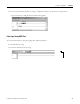
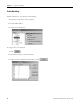
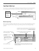
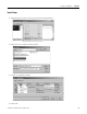
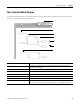
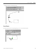
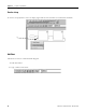
Table Of Contents
- 1756-QS001E-EN-P, Logix5000 Controllers Quick Start
- Summary of Changes
- Table of Contents
- 1 - Program and Test a Simple Project
- What You Need
- Before You Begin
- Follow These Steps
- Create a Project for the Controller
- Add Your I/O Modules
- Look at Your I/O Data
- Ladder Logic
- Enter a Function Block Diagram
- Assign Alias Tags for Your Devices
- Establish a Serial Connection to the Controller
- Download a Project to the Controller
- Select the Operating Mode of the Controller
- 2 - Organize a Project
- 3 - Program Add-On Instructions
- What You Need
- Follow These Steps
- Insert an Add-On Instruction
- Copy an Add-On Instruction Definition
- Import an Add-On Instruction Definition
- Access a Parameter That Is Not Visible
- Monitor or Change the Value of a Parameter of an Add-On Instruction
- View the Logic of an Add-On Instruction
- Edit and Monitor an Add-On Instruction
- Update an Add-On Instruction to a Newer Revision
- 4 - Program an Equipment Phase
- 5 - Program a Project Offline
- 6 - Document a Project
- 7 - Go Online to the Controller
- 8 - Program a Project Online
- 9 - Troubleshoot the Controller
- Index
- Back Cover
78 Publication 1756-QS001E-EN-P - October 2009
Chapter 5 Program a Project Offline
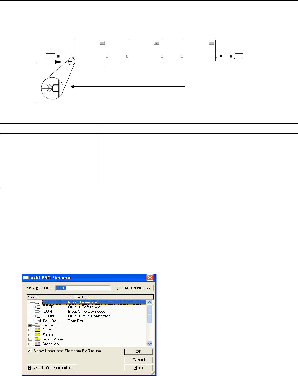
Use the Keyboard to Add an Element
You can add function block elements by using the computer keyboard.
1. Press Insert.
2. Type the mnemonic for the element and press Enter.
Item Description
H Assume data available indicator defines the data flow within the loop. The arrow indicates
that the data serves as input to the first block in the loop.
If a group of blocks are in a loop, you have to identify which block to execute first. Use the
Assume Data Available indicator to mark the input wire that creates the loop (the feedback
wire).
This input pin uses the output that block 3 produced on the previous scan.
12 3
H