
Quick Start Owner's manual
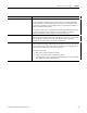

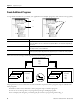
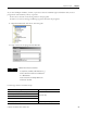
Table Of Contents
- 1756-QS001E-EN-P, Logix5000 Controllers Quick Start
- Summary of Changes
- Table of Contents
- 1 - Program and Test a Simple Project
- What You Need
- Before You Begin
- Follow These Steps
- Create a Project for the Controller
- Add Your I/O Modules
- Look at Your I/O Data
- Ladder Logic
- Enter a Function Block Diagram
- Assign Alias Tags for Your Devices
- Establish a Serial Connection to the Controller
- Download a Project to the Controller
- Select the Operating Mode of the Controller
- 2 - Organize a Project
- 3 - Program Add-On Instructions
- What You Need
- Follow These Steps
- Insert an Add-On Instruction
- Copy an Add-On Instruction Definition
- Import an Add-On Instruction Definition
- Access a Parameter That Is Not Visible
- Monitor or Change the Value of a Parameter of an Add-On Instruction
- View the Logic of an Add-On Instruction
- Edit and Monitor an Add-On Instruction
- Update an Add-On Instruction to a Newer Revision
- 4 - Program an Equipment Phase
- 5 - Program a Project Offline
- 6 - Document a Project
- 7 - Go Online to the Controller
- 8 - Program a Project Online
- 9 - Troubleshoot the Controller
- Index
- Back Cover

Publication 1756-QS001E-EN-P - October 2009 33
Program and Test a Simple Project Chapter 1
Mode Description
Program Logic is not executing, outputs are not controlled, and editing operations are available.
If you are configuring an output module, the owner controller is in Program Mode. Newly
received output values are ignored and all outputs will transition to their Program mode
state (which you can configure on the Configuration tab). The output module’s health LED
will flash green when in Program mode.
Input modules are always in Run mode and always report back input data to the controller. It
does not matter whether the owner controller is in Run or Program mode. The input
module’s health indicator is always solid green if a connection exists to it.
Run Logic is executing, inputs are read, logic is scanned, and outputs are controlled by the
application program and changes made through the data monitor or the I/O force table. The
actual I/O modules accept the output results of the application and set the outputs
accordingly. The keyswitch must be in the Remote or Run position.
Test Logic is executing, inputs are read, logic is scanned, and outputs are controlled by the
application program and changes made through the data monitor or the I/O force table. The
actual I/O modules will ignore the output results of the application. Some editing operations
are restricted. The keyswitch must be in the Remote position.
When going into Test mode:
• Input modules continue to update in Test mode.
• Produce/consume tags continue to update in Test mode.
• Test mode places all outputs in the project in the Program mode state (as configured
in the Configuration tab for module properties).