
Quick Start Owner's manual
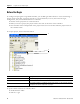
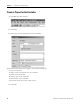
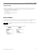
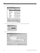
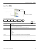
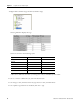
Table Of Contents
- 1756-QS001E-EN-P, Logix5000 Controllers Quick Start
- Summary of Changes
- Table of Contents
- 1 - Program and Test a Simple Project
- What You Need
- Before You Begin
- Follow These Steps
- Create a Project for the Controller
- Add Your I/O Modules
- Look at Your I/O Data
- Ladder Logic
- Enter a Function Block Diagram
- Assign Alias Tags for Your Devices
- Establish a Serial Connection to the Controller
- Download a Project to the Controller
- Select the Operating Mode of the Controller
- 2 - Organize a Project
- 3 - Program Add-On Instructions
- What You Need
- Follow These Steps
- Insert an Add-On Instruction
- Copy an Add-On Instruction Definition
- Import an Add-On Instruction Definition
- Access a Parameter That Is Not Visible
- Monitor or Change the Value of a Parameter of an Add-On Instruction
- View the Logic of an Add-On Instruction
- Edit and Monitor an Add-On Instruction
- Update an Add-On Instruction to a Newer Revision
- 4 - Program an Equipment Phase
- 5 - Program a Project Offline
- 6 - Document a Project
- 7 - Go Online to the Controller
- 8 - Program a Project Online
- 9 - Troubleshoot the Controller
- Index
- Back Cover
Publication 1756-QS001E-EN-P - October 2009 17
Program and Test a Simple Project Chapter 1
Look at Your I/O Data
I/O information is presented as a set of tags.
An I/O address follows this format.
Location :Slot :Type .Member .SubMember .Bit
= Optional
Where Is
Location Network location
LOCAL = same chassis or DIN rail as the controller
ADAPTER_NAME = identifies remote communication adapter or bridge module
Slot Slot number of I/O module in its chassis or DIN rail
Type Type of data
I = input
O = output
C = configuration
S = status
Member Specific data from the I/O module; depends on what type of data the module can store.
• For a digital module, a Data member usually stores the input or output bit values.
• For an analog module, a Channel member (CH#) usually stores the data for a channel.
SubMember Specific data related to a Member.
Bit Specific point on a digital I/O module; depends on the size of the I/O module (0-31 for a 32-point module)
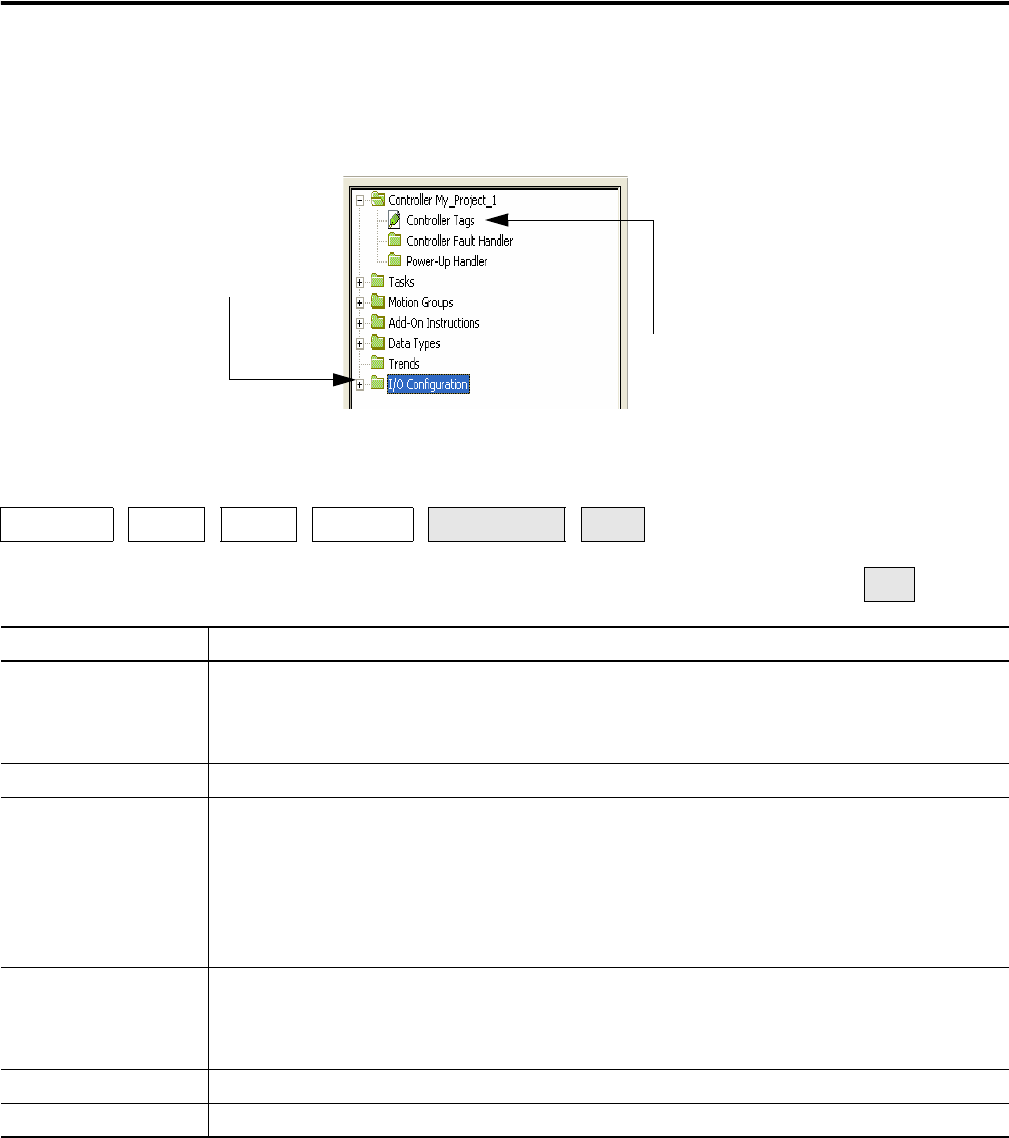
When you add a module to the I/O
Configuration folder…
…the software automatically creates
controller-scoped tags for the module.