
Quick Start Owner's manual
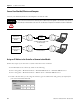
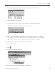
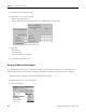
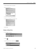
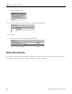
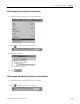
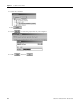
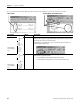
Table Of Contents
- 1756-QS001E-EN-P, Logix5000 Controllers Quick Start
- Summary of Changes
- Table of Contents
- 1 - Program and Test a Simple Project
- What You Need
- Before You Begin
- Follow These Steps
- Create a Project for the Controller
- Add Your I/O Modules
- Look at Your I/O Data
- Ladder Logic
- Enter a Function Block Diagram
- Assign Alias Tags for Your Devices
- Establish a Serial Connection to the Controller
- Download a Project to the Controller
- Select the Operating Mode of the Controller
- 2 - Organize a Project
- 3 - Program Add-On Instructions
- What You Need
- Follow These Steps
- Insert an Add-On Instruction
- Copy an Add-On Instruction Definition
- Import an Add-On Instruction Definition
- Access a Parameter That Is Not Visible
- Monitor or Change the Value of a Parameter of an Add-On Instruction
- View the Logic of an Add-On Instruction
- Edit and Monitor an Add-On Instruction
- Update an Add-On Instruction to a Newer Revision
- 4 - Program an Equipment Phase
- 5 - Program a Project Offline
- 6 - Document a Project
- 7 - Go Online to the Controller
- 8 - Program a Project Online
- 9 - Troubleshoot the Controller
- Index
- Back Cover
112 Publication 1756-QS001E-EN-P - October 2009
Chapter 7 Go Online to the Controller
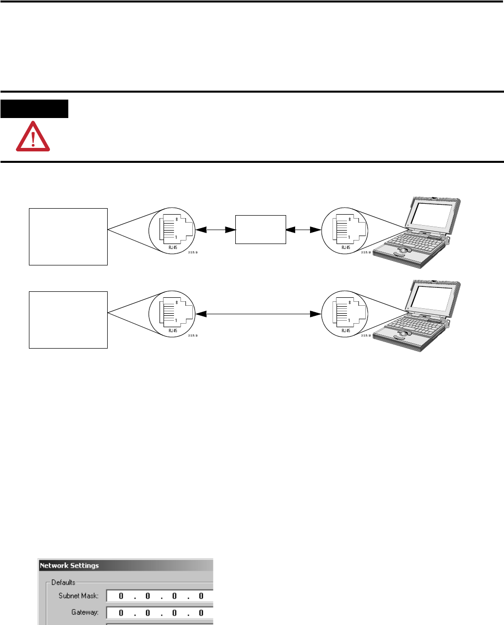
Connect Your EtherNet/IP Device and Computer
Connect your EtherNet/IP device and computer via ethernet cable.
Assign an IP Address to the Controller or Communication Module
Follow these steps if you do not have a serial connection to the controller.
1. Start BOOTP server software by either of the following:
• Start > Programs > Rockwell Software > BOOTP-DHCP Server > BOOTP-DHCP Server
• Start > Programs > Rockwell Software > RSLinx Tools > BOOTP-DHCP Server.
2. If this is the first time you are using the software, type the subnet mask and gateway (if required) for
your network and then click OK.
ATTENTION
If you connect or disconnect the communications cable with power applied to this module or any device on
the network, an electrical arc can occur. This could cause an explosion in hazardous location installations.
Logix5000
Controller or
Communication
Module
Crossover Ethernet Cable With
RJ-45 Connector
Logix5000
Controller or
Communication
Module
Standard Ethernet Cables With
RJ-45 Connector
Ethernet
Switch
– or –