Programming Manual Logix5000 Controllers Messages Catalog Numbers 1756-L1, 1756-L55, 1756-L61, 1756-L62, 1756-L63, 1769-L31, 1769-L32C, 1769L32E, 1769-L35CR, 1769-L35E, 1789-L60, PowerFlex 700S/SE
Important user information Read this document and the documents listed in the additional resources section about installation, configuration, and operation of this equipment before you install, configure, operate, or maintain this product. Users are required to familiarize themselves with installation and wiring instructions in addition to requirements of all applicable codes, laws, and standards.
Summary of changes The following table contains the changes made to this revision. Change Topic Updated sample project folder location.
Table of contents Preface Studio 5000 environment ..................................................................................... 7 Additional resources............................................................................................... 8 Chapter 1 Controller messages Introduction ............................................................................................................ 9 Supported data types ..............................................................................
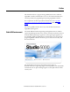
Preface This manual shows how to program message (MSG) instructions to and from Logix5000™ controllers. This manual is one of a set of related manuals that show common procedures for programming and operating Logix5000 controllers. For a complete list of common procedures manuals, refer to the Logix5000 Controllers Common Procedures Programming Manual, publication 1756PM001. The term Logix5000 controller refers to any controller that is based on the Logix5000 operating system.
Preface Additional resources These documents contain additional information concerning related Rockwell Automation products. Resource Description Industrial Automation Wiring and Grounding Guidelines, publication 1770-4.1 Provides general guidelines for installing a Rockwell Automation industrial system. Product Certifications webpage, available at http://ab.rockwellautomation.com Provides declarations of conformity, certificates, and other certification details.
Chapter 1 Controller messages Introduction This section describes how to transfer (send or receive) data between controllers by executing a message (MSG) instruction. It explains cache connections and buffers so you can correctly program the controller. Supported data types The following data types are supported when sending CIP messages. • SINT • INT • DINT • LINT • REAL In addition, you can send a message with any structure type that is predefined, module-defined, or user-defined.
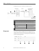
Chapter 1 Controller messages This diagram shows how the controller processes MSG instructions. Description The controller scans the MSG instruction and its rung-condition-in goes true. The message passes to a throttle that has 16 positions. If the throttle is full, the message remains enabled but is held until another controller scan. The System-overhead time slice executes and the message is pulled from the throttle to the message queue.
Controller messages Chapter 1 Description The controller scans the MSG instruction. The rung-condition-in for the MSG instruction is true. The EN bit is set. The MSG instruction attempts to enter the queue but 16 throttle positions exist. If all 16 are filled and a 17th message is executed, the message is enabled. The EW bit remains cleared. & The controller scans the MSG instruction. The rung-condition-in for the MSG instruction is false. The EN bit remains set.
Chapter 1 Controller messages The controller has the following limits on the number of connections that you can cache. If you have this software version and firmware revision Then you can cache 11.x or earlier • Block transfer messages for up to 16 connections. • Other types of messages for up to 16 connections. 12.x or later Up to 32 connections. If several messages go to the same device, the messages may be able to share a connection.
Controller messages Term Chapter 1 Definition The controller can have 10 to 40 unconnected buffers. • The default number is 10. • To increase the number of unconnected buffers, execute a MSG instruction that reconfigures the number of unconnected buffers. • Each unconnected buffer uses 1.2 KB of memory. • If all unconnected buffers are in use when an instruction leaves the message queue, an error occurs and data does not transfer.
Chapter 1 Controller messages Get or set the number of unconnected buffers To determine or change the number of unconnected buffers, use a MSG instruction. • The range is 10 to 40 unconnected buffers. • The default number is 10. • Each unconnected buffers uses 1.1 KB of memory. Get the number of unconnected buffers To determine the number of unconnected buffers that are currently available, configure a Message (MSG) instruction as follows.
Controller messages Chapter 1 Set the number of unconnected buffers As a starting value, set the number of unconnected buffers equal to the number of unconnected and uncached messages enabled at one time plus 5. The additional 5 buffers provide a cushion in case you underestimate the number of messages that are enabled at once. To change the number of unconnected buffers of the controller, configure a Message (MSG) instruction as follows.
Chapter 1 Controller messages Convert between INTs and DINTs Tag Name Type Description UCB_Set MESSAGE Control tag for the MSG instruction. Source_Array SINT[8] Source values for the MSG instruction, including the number of unconnected buffers that you want. In the Logix5000 controller, use the DINT data type for integers whenever possible. Logix5000 controllers execute more efficiently and use less memory when working with 32-bit integers (DINTs).
Controller messages Chapter 1 Write 16-bit integers DINTs from the project Buffer of INTs Data for the device DINT_Array[0] INT_Buffer[0] Word 1 DINT_Array[1] INT_Buffer[1] Word 2 DINT_Array[2] INT_Buffer[2] Word 3 Description An FAL instruction converts the DINTs from the Logix5000 controller to INTs. The MSG instruction writes the INTs from the temporary array to the device. Example: Read integer values from a PLC-5 controller If Condition_1 = 1 and Msg_1.
Chapter 1 Controller messages Example: Write integer values to a PLC-5 controller If Condition_2 = 1 then reset the FAL instruction. The FAL instruction sets INT_Buffer = DINT_Array. This converts the values to 16-bit integers (INTs). If Control_2.DN = 1 (FAL instruction has converted the DINTs to INTs) and Msg_2.EN = 0 (MSG instruction is not enabled) then write the integers in INT_Buffer (3 INTs) to the PLC-5 controller.
Chapter 2 Manage multiple messages Introduction You can use ladder logic to send groups of message (MSG) instructions in sequence. • To be processed, each MSG instruction must enter the message queue. • The queue holds 48 MSGs. • If more than 16 MSGs are enabled at one time, the message throttle prevents some of the messages from entering the message queue. If this occurs, the MSG is held until room exists on the queue for the controller to process the MSG.
Chapter 2 Manage multiple messages Restart the sequence If the MSGs in group 2 (last group) are currently enabled (Msg_Group.2 = 1) and Msg_4 is in the state of done or error and Msg_5 is in the state of done or error then restart the sequence of MSGs with the first group: Msg_Group.2 = 0. This disables the last group of MSGs. Msg_Group.0 = 1. This enables the first group of MSGs. Send the first group of MSGs If Msg_Group.0 changes from 0 -> 1 then send Msg_0. send Msg_1.
Manage multiple messages Chapter 2 Send the second group of MSGs If Msg_Group.1 changes from 0 -> 1 then send Msg_2. send Msg_3. Enable the next group of MSGs If the MSGs in group 1 are currently enabled (Msg_Group.1 = 1) and Msg_2 is in the state of done or error and Msg_3 is in the state of done or error then: Msg_Group.1 = 0. This disables the current group of MSGs. Msg_Group.2 = 1. This enables the next group of MSGs. Send the next group of MSGs If Msg_Group.1 changes from 0 -> 1 then send Msg_2.
Chapter 3 Send a message to multiple controllers Introduction You can program one message instruction to communicate with multiple controllers. To reconfigure a MSG instruction during runtime, write new values to the members of the MESSAGE data type. Important: In the MESSAGE data type, the RemoteElement member stores the tag name or address of the data in the controller that receives the message.
Chapter 3 Send a message to multiple controllers Configure the I/O configuration Although not required, it is recommended that you add the communication modules and remote controllers to the I/O configuration of the controller. This makes it easier to define the path to each remote controller. For example, once you add the local communication module, the remote communication module, and the destination controller, clicking Browse lets you select the destination.
Send a message to multiple controllers Chapter 3 2. Create the local_array tag, which stores the data in this controller. Create the MESSAGE_ CONFIGURATION data type Tag Name Type local_array data_type [length] where: data_type is the data type of the data that the message sends or receives, such as DINT, REAL, or STRING. length is the number of elements in the local array. Create a user-defined data type to store the configuration variables for the message to each controller.
Chapter 3 Send a message to multiple controllers Create the configuration array Store the configuration properties for each controller in an array. Before each execution of the MSG instruction, your logic loads new properties into the instruction. This sends the message to another controller. 1. To store the configuration properties for the message, create the following array.
Send a message to multiple controllers Chapter 3 Example: Type the path to the remote controller. OR Click Browse and browse to the remote controller. 3. In the message_config array, enter the tag name or address of the data in the first controller to receive the message. Enter the path and remote element for each additional controller. 4. Enter the path and remote element for each additional controller. Tag Name Value message_config {…} message_config[0] {…} message_config[0].
Chapter 3 Send a message to multiple controllers Get the size of the local array The SIZE instruction: • Counts the number of elements in local_array. • Counts the number of elements in Dimension 0 of the array. In this case, that is the only dimension. Local_array_length (DINT) stores the size (number of elements) of local_array. This value tells a subsequent rung when the message is sent to all controllers and to start with the first controller again.
Send a message to multiple controllers Configure the message Chapter 3 The following table explains how to configure the message.
Chapter 3 Send a message to multiple controllers Restart the sequence When the index equals the local_array_length, the controller sends the message to all other controllers. 1. The first CLR instruction sets the index equal to 0. This lets the logic load the configuration properties for the first controller into the MSG instruction and start the sequence of messages again. 2. The second CLR instruction sets the LocalIndex member of the MSG instruction equal to 0.
Index A array controller configuration 26 B block transfer guidelines 13 buffer for unconnected messages 12, 14 C cache connection 11 communicate message instruction 9 other controllers 9 connection cache 11 controller message properties 28 messages 9 M message cache connection 11 controller 9 convert between 16 and 32-bit data 16 example illustration 9 limits 10 manage multiple messages 19 processing 9 queue 10 to a single controller 9 to multiple controllers 23 unconnected buffer 12, 14 P processing m
Rockwell Automation support Rockwell Automation provides technical information on the web to assist you in using its products. At http://www.rockwellautomation.com/support you can find technical and application notes, sample code, and links to software service packs. You can also visit our Support Center at https://rockwellautomation.custhelp.com for software updates, support chats and forums, technical information, FAQs, and to sign up for product notification updates.