Programming Manual Logix5000 Controllers Information and Status Catalog Numbers 1756 ControlLogix, 1756 GuardLogix, 1768 Compact GuardLogix, 1768 CompactLogix, 1769 CompactLogix, 1789 SoftLogix, PowerFlex with DriveLogix
Important user information Read this document and the documents listed in the additional resources section about installation, configuration, and operation of this equipment before you install, configure, operate, or maintain this product. Users are required to familiarize themselves with installation and wiring instructions in addition to requirements of all applicable codes, laws, and standards.
Summary of changes This manual contains new and updated information. There are a number of minor changes throughout this publication that were made to clarify existing information. The major changes are listed below. Change Page Updated Entries Captured in the Controller Log to add new entries and correct existing entries. See Entries Captured in the Controller Logon page 25. Updated path to sample ladder logic. See Sample Ladder Logic File on page 39.
Table of contents Preface Studio 5000 Environment .................................................................................... 7 Additional Resources ............................................................................................. 8 Chapter 1 Connections Introduction ............................................................................................................ 9 Inhibit a Connection ........................................................................................
Table of Contents Chapter 4 Change detection Introduction .......................................................................................................... 47 Controller Change Detection ............................................................................ 47 ChangesToDetect ......................................................................................... 48 AuditValue......................................................................................................
Preface This manual describes how Logix5000 controllers use connections with other devices. This manual also describes status keywords and how to get controller information, such as memory resources. This manual is one of a set of related manuals that show common procedures for programming and operating Logix5000 controllers. For a complete list of common procedures manuals, Logix5000 Controllers Common Procedures Programming Manual, publication 1756-PM001.
Preface Additional resources These documents contain additional information concerning related Rockwell Automation products. Resource Description Industrial Automation Wiring and Grounding Guidelines, publication 1770-4.1. Provides general guidelines for installing a Rockwell Automation industrial system. Product Certifications webpage, available at http://ab.rockwellautomation.com. Provides declarations of conformity, certificates, and other certification details.
Chapter 1 Connections Introduction A Logix5000 controller uses connections for most, but not all, of its communication with other devices. Term Definition Connection A communication link between two devices, such as between a controller and an I/O module, PanelView terminal, or another controller. Connections are allocations of resources that provide more reliable communication between devices than unconnected messages. The number of connections that a single controller can have is limited.
Chapter 1 Connections Inhibit a connection In some situations, such as when initially commissioning a system, it is useful to disable portions of a control system and enable them as you physically connect the control system. The controller lets you inhibit individual modules or groups of modules, which prevents the controller from trying to communicate with the modules. Inhibiting a module breaks the connection to the module and prevents communication of I/O data.
Connections If you are Chapter 1 And you And Then Uninhibit a module (clear the check box) No fault occurs A connection is made to the module and the module is dynamically reconfigured (if the controller is the owner-controller) with the configuration you created for that module. If the controller is configured for listen-only, it cannot reconfigure the module. Fault occurs A connection is not made to the module. The module status information changes to indicate the fault condition.
Chapter 1 Connections Manage a connection failure If the controller loses communication with a module, data from that device does not update. When this occurs, the logic acts on the data in ways that may or may not be correct. You can program the controller to manage faults safely and efficiently. Outputs respond to the last, non-faulted state of the controlling inputs. To avoid potential injury and damage to machinery, make sure this does not create an unsafe operation.
Connections Chapter 1 Configure a major fault to occur You can configure modules to generate a major fault in the controller if they lose their connection with the controller. This interrupts the execution of logic and runs the Controller Fault Handler. If the Controller Fault Handler does not clear the fault, the controller shuts down. When you select Major Fault On Controller…Run Mode, the controller: • Must be connected to the module during the Program transition to Run mode.
Chapter 1 Connections If communication with a module times out, the controller produces the following warnings. • The I/O status indicator on the front of the controller flashes green. • A Warning ( ) icon shows over the I/O configuration folder and over the device that has timed out. • A module fault code is produced, which you can access through: • Module Properties window for the module. • GSV instruction.
Connections Example: Chapter 1 This rung checks the status of an I/O connection. The controller checks the entry status of the connection; any value other than 4 indicates that the connection is not functioning correctly. When the controller detects an error, the error code and information is trapped, and the controller tries to re-establish the connection.
Chapter 2 Determine controller memory information Introduction Depending on your type of controller, the memory of the controller may be divided into several areas.
Chapter 2 Determine controller memory information 2. On the Online toolbar (above the Controller Organizer), click the Controller Properties icon. 3. On the Controller Properties dialog box, click the Memory tab. 4. In the Estimated Data and Logic Memory area, view the memory information since the last estimate. 5. Click Estimate to re-estimate the amount of controller memory. 6. Click OK.
Determine controller memory information View run-time memory information Chapter 2 When you are online with a controller, the Memory tab shows the actual memory usage of the controller. While the controller is running, it uses additional memory for communication. The amount of memory the controller needs varies depending on the state of the communication. The Memory tab of the controller includes a Max Used entry for each type of memory.
Chapter 2 Determine controller memory information There are several ways to use logic to get memory information. Write Logic to Get Memory Information • Get memory information from the controller on page 20. • Choose the memory information on page 21. • Convert INTs to a DINT on page 22. Get memory information from the controller To get memory information from the controller, execute a Message (MSG) instruction. The following table lists configuration information for the instruction.
Determine controller memory information Chapter 2 Choose the memory information The MSG instruction returns the following information to INT_array (destination tag of the MSG). Important: The controller returns the values in 32-bit words. To see a value in bytes, multiply it by 4. If your controller does not divide its memory, the values show up as I/O memory. For the 1756-L55M16 controller, the MSG instruction returns two values for each logic memory category.
Chapter 2 Determine controller memory information Convert INTs to a DINT The MSG instruction returns each memory value as two separate INTs. • The first INT represents the lower 16 bits of the value. • The second INT represents the upper 16 bits of the value. To convert the separate INTs into one usable value, use a Copy (COP) instruction. In this operand Specify Which means Source First INT of the 2 element pair (lower 16 bits) Start with the lower 16 bits.
Chapter 3 Controller logging Introduction You use the controller logging feature to detect and log changes made to Logix5000 controllers without adding any auditing software. With controller logging, the controllers: • Detect changes and create logs entries containing information about the changes. • Store the log entries to removable media for later review. • Provide programmatic access to log entry counters to provide change detection information remotely.
Chapter 3 Controller logging Record Number Time Entry Description User Name 5 12-Feb 04:50:43 Change detection mask modified None None Old mask 16#FD60_CB89_029F_3566 16#FFFF_FFFF_FFFF_F FFF, New mask 16#FFFF_FFFF_FFFC_F FFF 6 12-Feb 04:58:29 Change Log entry added None None 16#FD60_CB89_029F_35BF Workstation FactoryTalk Extended Name ID Information Change Detection Audit Value Controller log header When the controller creates a log file on the removable media, it includes some header in
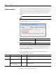
Controller logging Chapter 3 The following example shows controller log entries in a spreadsheet. Controller log files are stored in plain text files in TSV format, so no special tools are required to read them. You can open them in any text editor, or in a spreadsheet application such as Microsoft Excel. Entries captured in the controller log The following entries are detected and logged by the controller. These events are described in more detail in Controller log events on page 39.
Chapter 3 Controller logging • Change to constant tag configuration reset • Mode change • Major fault, major fault cleared • Program properties modified • Task properties modified • Controller timeslice modified • Removable media inserted or removed • Safety signature created or deleted • Safety locked or unlocked • Custom entry: User-defined logic to create a log entry, with user-defined entry description and extended information • Safety signature delete inhibited in Run mode • Sa
Controller logging Chapter 3 The controller does not attempt to write log entries to a full removable media card. If the removable media becomes full, the system behaves as if the removable media is not present. Controller log files are stored in plain text files in the TSV format, so no special tools are required to read them. You can open them in any text editor, or in a spreadsheet application such as Microsoft Excel.
Chapter 3 Controller logging You can retrieve the current state of the automatic write setting by using a CIP Generic message type and a service type of Controller Log Automatic Write Get. Use the following rung of ladder logic and message instruction configuration to get this value.
Controller logging Chapter 3 Save On Demand You can command the controller to write buffered entries to the CompactFlash card by using a message instruction with a CIP Generic message type and a service type of Controller Log Write To Media. A rung of ladder logic that sends this message and the configuration of the message instruction are shown in the following examples.
Chapter 3 Controller logging Controller logging counters Three counters, listed in the following table, provide real-time statistics about modifications to the controller. Counter Name Description Access Total Entry Count Number of entries added to the log since the last firmware update. GSV/SSV Unsaved Entry Count Number of entries in controller RAM not yet written to the CompactFlash card.
Controller logging Example: Chapter 3 Total Entry Count by using a Get System Value (GSV) ladder instruction The following rung of ladder logic shows how to set the Total Entry Count to a known value (in this example, 0) by using an SSV instruction. Example: Set the Total Entry Count to a Known Value ladder instruction Unsaved Entry Count The Unsaved Entry Count is the number of log entries that are in controller memory but have not yet been stored to the CompactFlash card.
Chapter 3 Controller logging Example: Retrieve the Unsaved Entry Count using a Get System Value (GSV) ladder instruction Execution Modification Count The Execution Modification Count tracks the number of changes that occur that can change the behavior of a running controller. You can configure the counter to include or exclude force changes. The events that cause the Execution Modification Count to increment include the following.
Controller logging Example: Chapter 3 Retrieve the Execution Modification Count by using a GSV ladder instruction The following rung of ladder logic shows how to set the Execution Modification Count to a known value. Example: Ladder instruction to set the Execution Modification Count to a known value You use a message instruction of message type CIP Generic and a service type of Controller Log Config Execution Set to configure whether the Execution Modification Count includes forces.
Chapter 3 Controller logging Example: Controller Log Config Execution Set ladder instruction and configuration dialog box The Source Element should be of data type DINT. You also use a message instruction to retrieve the current value of this configuration. This message uses a message type of CIP Generic and a service type of Controller Log Config Execution Get.
Controller logging Example: Chapter 3 Controller Log Config Execution Get ladder instruction and configuration dialog box The Destination tag should be of type DINT. Log file storage When a log file is written to the CompactFlash card, it is stored at \Logix\XXXXXXXX\Logs\VYY_ZZ, where XXXXXXXX is the eight-digit serial number of the controller and YY_ZZ is the revision number of the firmware (major_minor revision).
Chapter 3 Controller logging Log File Location The file is named ControllerLog_yyy.txt, where yyy is a sequential number from 000…999. The controller adds to the log file until it reaches a size greater than 1 MB. At that point, the next write of the controller log causes a new file to be created with the next sequence number. When there are 1000 files larger than 1 MB, no more logs are created.
Controller logging Chapter 3 Log file format The following table lists the information that is contained in the controller log file.
Chapter 3 Controller logging Create custom log entries You can add custom entries to the controller log using a message instruction. The message instruction uses a CIP Generic message type and a service type of Controller Log Add Entry. The source element of this message should be a tag of a user-defined data type. The user-defined data type should contain two string members. The controller writes the first string to the log entry's Description field.
Controller logging Chapter 3 Sample ladder Logic file In the Logix Designer application, there is a controller logging sample ladder file. If you installed the sample files during the installation, you can open the sample files from the Help menu. On the Help menu, select Vendor Sample Projects. Controller log events The following table describes the events that the controller stores in the controller log.
Chapter 3 Controller logging Entry Information Logged Store to removable media • Time Stamp • Entry Description: Project store • UserName • Workstation Name • FactoryTalk Login Id • Extended Information: Project Online edits tested or assembled • Time Stamp • Entry Description: Online edits modified controller program • UserName • Workstation Name • FactoryTalk Login Id • Extended Information: None • Edits logged are: − Test Program Edits − UnTest Program Edits − Assemble Program Edits − Accept Progr
Controller logging Entry Information Logged I/O forces modified • Time Stamp Chapter 3 • Entry Description: I/O force value changed • UserName • Workstation Name • FactoryTalk Login Id • Extended Information: Tag SFC forces enabled • Time Stamp • Entry Description: SFC forces enabled • UserName • Workstation Name • FactoryTalk Login Id • Extended Information: None SFC forces disabled • Time Stamp • Entry Description: SFC forces disabled • UserName • Workstation Name • FactoryTalk Login Id • Extende
Chapter 3 Controller logging Entry Information Logged Firmware update from removable media • Time Stamp • Entry Description: Firmware update from removable media attempted • UserName: Local • Workstation: None • FactoryTalk Login Id: None • Extended Information: Old revision , New revision , where the major and minor revision numbers are each two digits.
Controller logging Entry Information Logged Major faults cleared • Time Stamp Chapter 3 • Entry Description: All major faults cleared • UserName • Workstation Name • FactoryTalk Login Id • Extended Information: None Major faults cleared through key switch • Time Stamp • Entry Description: All major faults cleared • UserName: Local • Workstation Name: None • FactoryTalk Login Id: None • Extended Information: None Program properties modified • Time Stamp • Entry Description: Program properties modifi
Chapter 3 Controller logging Entry Information Logged Controller time slice modified • Time Stamp • Entry Description: Controller timeslice modified • UserName • Workstation Name • FactoryTalk Login Id • Extended Information • Changes logged: − System Overhead Time Slice − During unused System Overhead Time Slice radio buttons Removable media removed • Time Stamp • Entry Description: Removable media removed • UserName: Local • Workstation Name: None • FactoryTalk Login Id: None • Extended Information
Controller logging Entry Information Logged Safety unlocked • Time Stamp Chapter 3 • Entry Description: Safety unlock • UserName • Workstation Name • FactoryTalk Login Id • Extended Information: None Custom entry • Time Stamp • Entry Description: maximum 40 characters • UserName • Workstation Name • FactoryTalk Login Id • Extended Information: , maximum 82 characters Constant tag data changed • Time Stamp • Entry Description: Constant tag data changed • Us
Chapter 3 Controller logging Entry Information Logged Safety signature delete allowed in Run mode • Time Stamp • Entry Description: Safety signature delete allowed in Run mode • UserName • Workstation Name • FactoryTalk Login Id • Extended Information: None Audit Value Mask Modified • Time Stamp • Entry Description: Change detection mask modified • UserName • Workstation Name • FactoryTalk Login Id • Extended Information: Old mask: 0xFFFF_FFFF_FFFF_FFFF New mask: 0xFFFF_FFFF_FFFF_DFFF Log Collected
Chapter 4 Change detection Introduction You can use the controller change detection feature as an additional means of detecting changes made to Logix5000 controllers. • A unique audit value is generated when a project is downloaded to the controller. • When a change is detected in the controller, a new audit value is generated. • ChangesToDetect mask allows you to programmatically configure the events to monitor for changes.
Chapter 4 Change detection Attribute Name Description Access ChangesToDetect Used to specify which changes are monitored. When a monitored change occurs, the Audit Value is updated. GSV/SSV ChangesToDetect The ChangesToDetect mask is a 64-bit value. Each bit of the ChangesToDetect mask corresponds to a particular event that could cause the Audit Value to change. See ChangesToDetect Format on page 50.
Change detection Tip: Chapter 4 Rockwell recommends using the DINT[2] data type to avoid limitations when working with LINT data types in Rockwell Automation controllers. You can use the Message Configuration dialog box to read or write to the ChangesToDetect attribute through CIP Generic Messages. For complete information on how to access data using an MSG instruction, refer to the Logix5000 Controllers Messages Programming Manual, publication 1756PM012.
Chapter 4 Change detection access data using an MSG instruction, refer to the Logix5000 Controllers Messages Programming Manual, publication 1756-PM012. Use these settings to read the Audit Value attribute using the Message Configuration. If you want to Get AuditValue in this property Type or select Message Type CIP Generic Service Type Audit Value Get Source Leave blank Destination tag_name of type DINT[2] or LINT 1 This tag contains the AuditValue for the controller.
Change detection Change detection in Logix Designer Application Chapter 4 Bit number Event description 22 Removable media inserted 23 Safety signature created 24 Safety signature deleted 25 Safety lock 26 Safety unlock 27 Constant Tag value changed 28 Multiple constant Tag values changed 29 Constant Tag attribute cleared 30 Constant Tag attribute set 31 Custom Log Entry Added 32 Correlation Affected.
Chapter 4 Change detection To edit the Changes To Detect field, type a new value. To select the events to monitor for changes from a list, click Configure to open the Configure Changes to Detect dialog box. For additional information on configuring the settings on the Security tab, refer to the Logix5000 Security Programming Manual, publication 1756-PM016 or the online help for the Logix Designer application. Tip: 52 To configure Change Detection programmatically use SSV, GSV or MSG instructions.
Chapter 5 Access status information Introduction The controller supports status keywords you can use in your logic to monitor specific events. • The status keywords are not case sensitive. • Because the status flags can change quickly, the Logix Designer application does not display the status of the flags. For example, even when a status flag is set, an instruction that references that flag is not highlighted. • You cannot define a tag alias to a keyword.
Chapter 5 Access status information Status of S:FS when the project has an SFC The state of S:FS depends on the status of the SFC. • If you use S:FS in an action of a sequential function chart (SFC), S:FS is set (on) for one scan each time the step goes active. S:FS = step_name.FS. • If the SFC calls a routine, S:FS is set (on) for one scan each time the step that calls the routine goes active. S:FS = step_name.FS. If the SFC does not call a routine, S:FS is set (on) for the first scan of the task.
Access status information Chapter 5 4. In the Type in the keyword to find field, type GSV/SSV objects and click Display. 5. In the GSV/SSV Objects help window, click the object you need.
Chapter 5 Access status information To Enter this instruction Get the value of an attribute GSV Set the value of an attribute SSV 9. Assign the required operands to the instruction. For this operand Select Class name Name of the object. Instance name Name of the specific object (for example, name of the required I/O module, task, message). • Not all objects require this entry. • To specify the current task, program, or routine, select THIS. Attribute name Name of the attribute.
Index A access status information 55 AuditValue 51 B bridge module connection 10 C Change Detection 49 ChangesToDetect 50 communicate other controllers 9 CompactFlash log 27 configure I/O module 10 connection failure 11 fault checkbox 13 I/O fault 11 inhibit 10 major fault 13 monitor 13 controller log entries 23 memory information 17 D DINT 22 F fault communication loss 11 I/O connection 11 file log 36 G GSV/SSV objects 56 I I/O module communication loss 11 connection fault 11 inhibit 10 path configur
Index O objects data storage 56 P path connection route 9 S status access data 55 memory 17 monitor 56 system data access 56 58 Rockwell Automation Publication 1756-PM015F-EN-P – October 2014
Rockwell Automation support Rockwell Automation provides technical information on the web to assist you in using its products. At http://www.rockwellautomation.com/support you can find technical and application notes, sample code, and links to software service packs. You can also visit our Support Center at https://rockwellautomation.custhelp.com for software updates, support chats and forums, technical information, FAQs, and to sign up for product notification updates.