Programming Manual Logix5000 Controllers Add On Instructions Catalog Numbers 1756 ControlLogix, 1756 GuardLogix, 1768 CompactLogix, 1768 Compact GuardLogix, 1769 CompactLogix, 1789 SoftLogix, PowerFlex with DriveLogix
Important user information Read this document and the documents listed in the additional resources section about installation, configuration, and operation of this equipment before you install, configure, operate, or maintain this product. Users are required to familiarize themselves with installation and wiring instructions in addition to requirements of all applicable codes, laws, and standards.
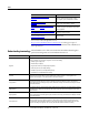
Summary of changes This manual contains new and updated information. The following table contains the changes made to this revision.
Table of contents Preface Studio 5000 environment...........................................................................................9 Additional resources.....................................................................................................9 Understanding terminology.................................................................................... 10 Chapter 1 Designing Add-On Instructions Introduction...............................................................................
Table of Contents Using standard and safety tags ........................................................................ 34 Data access control............................................................................................. 34 Constant values................................................................................................... 35 External Access....................................................................................................
Table of Contents Verifying individual scan modes..................................................................... 59 Defining source protection for an Add-On Instruction ................................. 60 Enable the source protection feature............................................................. 60 Generating an Add-On Instruction signature.................................................... 61 Generating, removing, or copying an instruction signature....................
Table of Contents Index 8 Importing an Add-On Instruction........................................................................ 94 Import considerations....................................................................................... 94 Import configuration ........................................................................................ 95 Updating an Add-On Instruction to a newer revision through import......
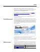
Preface This manual shows how to use Add-On Instructions, which are custom instructions that you design and create, for the Logix Designer application. This manual is one of a set of related manuals that show common procedures for programming and operating Logix5000 controllers. For a complete list of common procedures manuals, refer to the Logix5000 Controllers Common Procedures Programming Manual, publication 1756-PM001.
Preface Resource Description Compact GuardLogix Controllers User Manual, publication 1768-UM002C Guide for using Compact GuardLogix™ controllers. Describes the Compact GuardLogix-specific procedures used to configure, operate, and troubleshoot controllers. GuardLogix Controllers User Manual, publication 1756-UM020 Provides GuardLogix-specific procedures to use to configure, operate, and troubleshoot controllers.
Preface Term Definition Passed by value When an argument is passed to a parameter by value, the value is copied in or out of the parameter when the Add-On Instruction executes. The value of the argument does not change from external code or HMI interaction outside of the Add-On Instruction itself. Module reference parameter A module reference parameter is an InOut parameter of the MODULE data type that points to the Module Object of a hardware module.
Chapter 1 Designing Add-On Instructions Introduction Add-On Instructions are available beginning with RSLogix 5000, version 16. Add-On Instructions are custom instructions that you design and create. Beginning in RSLogix 5000, version 18, high integrity and safety Add-On Instructions are available. About Add-On Instructions With Add-On Instructions, you can create new instructions for sets of commonly-used logic, provide a common interface to this logic, and provide documentation for the instruction.
Chapter 1 Designing Add-On Instructions An Add-On-Instruction can be used across multiple projects. You can define the instructions, the instructions can be provided to you by someone else, or they can be copied from another project. Once defined in a project, they behave similarly to the built-in instructions already available in the Logix Designer application.
Designing Add-On Instructions Chapter 1 Class information for safety controller projects appears on the General tab as well. The class can be standard or safety. Safety Add-On Instructions must meet requirements specific to safety applications. See Safety Add-On Instructions on page 23 for more information.
Chapter 1 Designing Add-On Instructions Parameters The parameters define the instruction interface; that is, how the instruction appears when used. The parameter order defines the order that the parameters appear on the instruction call. Local tags The Local Tags tab defines tags that are used by the logic within the Add-On Instruction and are not visible outside the instruction. Other Add-On Instructions or programs in the project cannot access these tags.
Designing Add-On Instructions Chapter 1 See Creating an Alias Parameter for a Local Tag on page 31. Data Type Parameters and local tags are used to define the Data Type that is used when executing the instruction. The software builds the associated Data Type. The software orders the members of the Data Type that correspond to the parameters in the order that the parameters are defined. Local tags are added as hidden members.
Chapter 1 Designing Add-On Instructions Logic routine The logic routine of the Add-On Instruction defines the primary functionality of the instruction. It is the code that executes whenever the instruction is called. The following image is the interface of an Add-On Instruction and its primary logic routine that defines what the instruction does.
Designing Add-On Instructions Chapter 1 Optional Scan Modes routines You can define additional routines for scan mode behavior. Instruction signature The instruction signature consists of an ID number that identifies the contents of the Add-On Instruction and a timestamp that identifies the specific date and time at which the instruction signature was generated or a signature history entry was made (whichever came last).
Chapter 1 Designing Add-On Instructions Once generated, the instruction signature seals the Add-On Instruction, preventing it from being edited while the signature is in place. In addition, when a sealed safety Add-On Instruction is downloaded for the first time, a SIL 3 safety instruction signature is automatically generated. The safety instruction signature is an ID number that identifies the execution characteristics of the safety Add-On Instruction.
Designing Add-On Instructions Chapter 1 Change history The Change History tab displays the creation and latest edit information that is tracked by the software. The By fields show who made the change based on the Windows user name at the time of the change. Help The name, revision, description, and parameter definitions are used to automatically build the Instruction Help. Use the Extended Description Text to provide additional Help documentation for the Add-On Instruction.
Chapter 1 Designing Add-On Instructions The Instruction Help Preview shows how your instruction will appear in the various languages, based on parameters defined as required or visible. Considerations for Add-On Instructions When deciding whether to develop an Add-On Instruction, consider the following aspects. Instruction functionality Complex instructions tend to be highly application specific and not reusable, or require extensive configuration support code.
Designing Add-On Instructions Chapter 1 direct programmatic access to controller or program scope tags. This lets the Add-On Instruction be a standalone component that can execute in any application that calls it by using the parameters interface. It can be validated once and then locked to prevent edits. Safety Add-On Instructions Safety Add-On Instructions are used in the safety task of GuardLogix safety controllers.
Chapter 1 Designing Add-On Instructions • Copy the instruction signature • Create or copy a signature history entry • Create instances of the Add-On Instruction • Download the instruction • Remove the instruction signature • Print reports The instruction signature does not prevent referenced Add-On Instructions or User-defined Data Types from being modified.
Designing Add-On Instructions Chapter 1 Each of the programming languages supported in Logix Designer application is targeted for different types of applications and programming styles. In general, Ladder Diagram executes simple Boolean logic, timers, and counters the fastest. Function Block Diagrams and Structured Text may be more efficient if you take advantage of the more advanced process and drives instructions available in those languages.
Chapter 1 Designing Add-On Instructions Limits cannot be accessed inside Add-On Instruction logic. The maximum data instance supported (which includes Inputs, Outputs, and local tags) is two megabytes. The data type size is displayed on the bottom of the Parameters and Local Tags tab in the Add-On Instruction Definition. Runtime editing Add-On Instructions can only be edited offline.
Designing Add-On Instructions Chapter 1 Aspect Main Routine Subroutine Add-On Instruction Accessibility N/A Within program (multiple copies, one for each program) Anywhere in controller (single copy for the entire project) Parameters N/A Pass by value Pass by value with Input and Output parameters Numeric parameters N/A No conversion, user must manage Automatic data type conversion for Input and Output parameters Parameters data types N/A Atomic, arrays, structures Atomic for any parame
Chapter 1 Designing Add-On Instructions Programmatic access to data Input and Output parameters and local tags are used to define an instruction-defined data type. Each parameter or local tag has a member in the data type, although local tag members are hidden from external use. Each call to an Add-On Instruction uses a tag of this data type to provide the data instance for the instruction's execution.
Designing Add-On Instructions Chapter 1 Safety application instructions, such as Safety Mat (SMAT), may be used in safety Add-On Instructions only. For detailed information on safety application instructions, refer to the GuardLogix Safety Application Instruction Set Safety Reference Manual, publication 1756-RM095. In addition, the following instructions may be used in an Add-On Instruction, but the data instances must be passed as InOut parameters.
Chapter 1 Designing Add-On Instructions Attribute Name Data Type Attribute Description MajorRevision DINT Major revision number of the Add-On Instruction MinorRevision DINT Minor revision number of the Add-On Instruction Name String Name of the Add-On Instruction RevisionExtendedText String Text describing the revision of the Add-On Instruction Vendor String Vendor that created the Add-On Instruction LastEditDate LINT Date and time stamp of the last edit to an Add-On Instruction Signa
Designing Add-On Instructions Chapter 1 Selecting a data type for a parameter The Logix5000 controllers perform DINT (32 bit) and REAL (32 bit) math operations, which causes DINT data types to execute faster than other integer data types. Data conversion rules of SINT to INT to DINT are applied automatically, and can add overhead. Whenever possible, use DINT data types for the Add-On Instruction Input and Output parameters.
Chapter 1 Designing Add-On Instructions Tip: When you monitor an array InOut parameter inside of the logic routine, the parameter definition is used to determine the size of the array. For example, assume you have defined an InOut parameter to be a 10-element array of DINTs and the end user passes in an array of 100 DINTs. Then if you open the Add-On Instruction logic, select the appropriate context for that call, and monitor the array parameter, only 10 elements will be displayed.
Chapter 1 Designing Add-On Instructions The following picture shows Simulation instruction in a ladder. • If you want the parameter’s value displayed on the instruction face in Ladder, set the parameter as visible. • An Output parameter of the BOOL tag type that is not required, but visible, will show as a status flag on the right side of the block in Ladder. This can be used for status flags like DN or ER.
Chapter 1 Designing Add-On Instructions Tip: When you are using your Add-On Instructions, the Visible setting may be overridden in Function Block Diagram routines if the parameter is not required or already wired. Overriding the visibility at the instruction call does not affect this definition configuration.
Designing Add-On Instructions Chapter 1 Constant values InOut parameters may be designated as constant value tags to prevent their data from being modified by controller logic. If the logic of an Add-On Instruction contains a write operation to a constant value parameter, the Add-On Instruction does not verify in the Add-On Instruction definition context. External Access External Access defines the level of access that is allowed for external devices, such as an HMI, to see or change tag values.
Chapter 1 Designing Add-On Instructions Planning your Add-On Instruction design Take time to plan your instruction design. Advance planning can identify issues that need to be addressed. When defining the requirements of an instruction, you are also determining the interface. Keep the following aspects in mind when defining your instruction requirements and creating your Add-On Instruction.
Designing Add-On Instructions Chapter 1 Parameters • What data needs to be passed to the instruction? • What information needs to be accessible outside of the instruction? • Do alias parameters need to be defined for data from local tags that needs to be accessible from outside the Add-On Instruction? • How does the parameters display? The order of the parameters defines the appearance of instruction.
Chapter 1 Designing Add-On Instructions • Identify local tags you might use in your instruction. Local tags are useful for items such as intermediate calculation values that you do not want to expose to users of your instruction. • Do you want to create an alias parameter to provide outside access to a local tag? Programming languages • What language do you want to use to program your instruction? The primary logic of your instruction will consist of a single routine of code.
Chapter 2 Defining Add-On Instructions Creating an Add-On Instruction Follow these steps to create a New Add-On Instructions. 1. Open a new or existing project. 2. Right-click the Add-On Instructions folder in the Controller Organizer and select New Add-On Instruction. 3. In the Name box, type a unique name for the new instruction. The name can be up to 40 characters long. It must start with a letter or underscore and must contain only letters, numbers, or underscores.
Chapter 2 Defining Add-On Instructions The Class field is available on the Add-On Instructions dialog box for safety controller projects. 6. In the Type box, select a programming language for Add-On Instruction logic. The language Type defaults to Ladder Diagram for safety Add-On Instructions. 7. In Revision box, assign a Revision level for the instruction. 8. (Optional) In the Revision Note box, type a Revision note. 9. (Optional) In the Vendor box, add information about the Vendor. 10.
Defining Add-On Instructions Chapter 2 4. In the Data Type list, choose the type based on the parameter usage: • An Input parameter is a passed by value into the Add-On Instruction and must be a SINT, INT, DINT, REAL, or BOOL data type. • An Output parameter is a passed by value out of the Add-On Instruction and must be a SINT, INT, DINT, REAL, or BOOL data type. • An InOut parameter is a passed by reference into the Add-On Instruction and can be any data type including structures and array.
Chapter 2 Defining Add-On Instructions 11. In the Constant list, select InOut parameters check box you want to designate as constant values. 12. Repeat for additional parameters. Tip: You can also create parameters by using the Tag Editor, New Parameter or Local Tag dialog box, or by right-clicking a tag name in the logic of your routine. The order that you create the parameters is how they appear in the data type and on the instruction face.
Defining Add-On Instructions Chapter 2 • Program parameters that reference a module must connect to a module, and cannot reference other module reference parameters. • Module reference parameters must be program or Add-on Instruction scope, not controller scope. Tip: You cannot create a module reference tag. You can only reference modules using an InOut parameter of the MODULE data type. 1. In the Controller Organizer, right-click an Add-On Instruction and select Open Definition. 2.
Chapter 2 Defining Add-On Instructions Creating local tags Use the Add-On Instruction Definition Editor to create the local tags for your instructions. Local tags contain data that will be used by your Add-On Instruction but that you do not want exposed to the user of your instruction. Local tags do not appear in the data structure for an Add-On Instruction because they are hidden members.
Defining Add-On Instructions Chapter 2 Default values are loaded from the Add-On Instruction definition into the tag of the Add-On Instruction data type when it is created or any time a new tag is added to the Add-On Instruction.
Chapter 2 Defining Add-On Instructions Updates to arguments following parameter edits If you edit an Add-On Instruction by adding, deleting, renaming, reordering, or changing the status or usage type of one or more parameters, RSLogix 5000 software, version 18 and later, automatically updates the arguments on calls to the instruction.
Defining Add-On Instructions Chapter 2 parameters have the same name, but different operational definitions, importing or pasting may impact the behavior of the instruction. Copying parameter or local tag default values In RSLogix 5000 software, version 18 or later, you can copy either parameter or local tag default values to all tags of the Add-On Instruction data type or just to specific tags. You can do so only when you are offline.
Chapter 2 Defining Add-On Instructions If you want to select which specific tags and values to copy, click the pull-down arrow of the copy default values icon and select Copy Specified Values. The Copy Default Values dialog box shows the current default values for the parameters and local tags, and the instance tags where the Add-On Instruction is used or referenced. Select the check boxes to select which values to copy to which tags, and click OK.
Defining Add-On Instructions Chapter 2 3. Edit your logic by using the available language editors. Execution considerations for Add-On Instructions An Add-On Instruction is executed just like any other routine belonging to a particular program. Because another task can preempt a program containing an Add-On Instruction that is being executed, an Add-On Instruction may be interrupted prior to completing its execution.
Chapter 2 Defining Add-On Instructions Scan Mode Description Prescan Occurs when the controller either powers up in Run mode or transitions from Program to Run. Instructions in the controller may or may not have logic that executes only when that instruction is executed in Prescan mode. Postscan(1) Occurs as a result of an Action in a Sequential Function Chart (SFC) routine becoming inactive if SFCs are configured for Automatic Reset.
Defining Add-On Instructions Chapter 2 Prescan routine When the controller transitions from Program mode to Run mode or when the controller powers up in Run mode, all logic within the controller is executed in Prescan mode. During this scan, each instruction may initialize itself and some instructions also initialize any tags they may reference. For most instructions, Prescan mode is synonymous with scanning false. For example, an OTE instruction clears its output bit when executed during Prescan mode.
Chapter 2 Defining Add-On Instructions 3. Click New for Prescan routine. 4. On the New Scan Mode Routine dialog box, from the Type list, select the type of programming language; Ladder Diagram, Function Block, or Structured Text. 5. In the Description box, type the Prescan behavior. 6. Click OK to create the routine and return to the Scan Modes tab. 7. Define if the prescan routine executes (or not) by checking or clearing Execute Prescan routine after the logic routine is prescanned check box.
Defining Add-On Instructions Chapter 2 Postscan routine Postscan mode occurs only for logic in a Sequential Function Chart Action when the Action becomes inactive and the SFC language is configured for Automatic Reset (which is not the default option for SFC). When an SFC Action becomes inactive, then the logic in the Action is executed one more time in Postscan mode. This mode is similar to Prescan in that most instructions simply execute as if they have a false condition.
Chapter 2 Defining Add-On Instructions 4. On the New Scan Mode Routine dialog box, from the Type list, select the type of programming language; Ladder Diagram, Function Block, or Structured Text. 5. In the Description box, type the Postscan behavior. 6. Click OK to create the routine and return to the Scan Modes tab. 7. Define if the postscan routine executes (or not) by checking or clearing Execute Postscan routine after the logic routine is postscanned.
Defining Add-On Instructions Chapter 2 • Values are passed to Input parameters from their arguments in the instruction call. • Values are passed out of Output parameters from their arguments in the instruction call. If the EnableInFalse routine is not enabled, the only action performed for the Add-On Instruction in the false condition is that the values are passed to any required Input parameters in ladder logic. Follow these steps to create an EnableInFalse routine.
Chapter 2 Defining Add-On Instructions 4. On the New Scan Mode Routine dialog box, from the Type list, select the type of programming language; Ladder Diagram, Function Block, or Structured Text. 5. In the Description box, type the EnableInFalse behavior. 6. Click OK to create the routine and return to the Scan Modes tab. 7. Define if EnableIn False routine executes (or not) by checking or clearing Execute EnableInFalse routine. The EnableInFalse routine can now be edited like any other routine.
Defining Add-On Instructions Chapter 2 EnableIn parameter and ladder diagrams In the ladder diagram environment, the EnableIn parameter reflects the rung state on entry to the instruction. If the rung state preceding the instruction is True (1), the EnableIn parameter will be True and the primary logic routine of the instruction will be executed. Likewise, if the rung state preceding the instruction is False (0), the EnableIn parameter will be False and the primary logic routine will not be executed.
Chapter 2 Defining Add-On Instructions If any parameters or tags become unverified due to the change of class, they are identified on the Parameters and Local Tags tabs of the Add-On Instruction Editor. If any of the restrictions for safety Add-On Instructions are violated by changing the class from standard to safety, one of the following errors is displayed and the change does not succeed: • Routines must be of Ladder Diagram type. • Safety Add-On Instructions do not support the Postscan routine.
Defining Add-On Instructions Chapter 2 Monitoring logic with data context views You can simplify the online monitoring and troubleshooting of your Add-On Instruction by using Data Context views. The Data Context selector lets you select a specific call to the Add-On Instruction that defines the calling instance and arguments whose values are used to visualize the logic for the Add-On Instruction.
Chapter 2 Defining Add-On Instructions Defining source protection for an Add-On Instruction Instruction Description True This is simply the execution of the main logic routine. False In a ladder logic target routine, this entails placing an XIC before an instance of the instruction and evaluating instruction results when the XIC is false. In a Function Block target routine, this entails executing an instance of the instruction with the EnableIn parameter set to zero (0).
Defining Add-On Instructions Chapter 2 For procedures on how to use the Source Protection feature, refer to the Logix5000 Controllers Security Programming Manual, publication 1756-PM016. Generating an Add-On Instruction signature The Signature tab on the Add-On Instruction Definition Editor lets you manage the instruction signature, create signature history entries, and view the safety instruction signature, if it exists. Instruction signatures are applied to the definition of the Add-On Instruction.
Chapter 2 Defining Add-On Instructions 1. On the Signature tab on the Add-On Instruction Definition Editor, click Add to History. 2. In the Create History Entry description box, type up to 512 characters long, for the entry. 3. Click OK. Tip: To facilitate record-keeping, you can copy the entire signature history to the clipboard by selecting all the rows in the signature history and choosing Copy from the Edit menu. The data is copied in tab separated value (TSV) format.
Defining Add-On Instructions Tip: Chapter 2 When an instruction is sealed, the instruction signature is displayed on the faceplate of the instruction in the Ladder Diagram Editor and the Function Block Diagram Editor. You can turn off the display of the instruction signature in the Workstation Options dialog box of Logix Designer application.
Chapter 2 Defining Add-On Instructions This is an example of the Extended Description Text field in the Help tab on the Add-On Instruction Definition Editor. This area lets you create directions on how to use and troubleshoot your instruction. The Instruction Help Preview window shows how your text will look as generated instruction help.
Defining Add-On Instructions Chapter 2 a. For the logic routine, describe execution of the instruction when EnableIn is true. b. For the EnableInFalse routine (if one exists), describe actions that will take place when EnableIn is false, such as any outputs that get cleared. c. For the Prescan routine (if one exists), briefly describe actions that will take place during the Prescan routine, such as initialization of any parameters. d.
Chapter 2 Defining Add-On Instructions Project documentation With RS Logix 5000 software, version 17 and later, you have the option to display project documentation, such as tag descriptions and rung comments in any supported localized language. You can store project documentation for multiple languages in a single project file rather than in language-specific project files.
Defining Add-On Instructions Chapter 2 Project documentation that supports multiple translations includes these variables: • Component descriptions in tags, routines, programs, equipment phases, user-defined data types, and Add-On Instructions • Engineering units and state identifiers added to tags, user-defined data types, or Add-On Instructions • Trends • Controllers • Alarm Messages (in configuration of ALARM_ANALOG and ALARM_DIGITAL tags) • Tasks • Property descriptions for module in the
Chapter 2 Defining Add-On Instructions If the stop pushbutton is pressed (opened), then the motor stops. The following screen capture shows the General tab for the Motor Starter Add-On Instruction. The following screen capture shows the Parameter tab for the Motor Starter Example Definition Editor.
Defining Add-On Instructions Chapter 2 The following screen capture shows the Motor Starter Example ladder logic.
Chapter 2 Defining Add-On Instructions The following diagrams show the Motor Starter instruction called in three different programming languages. First is Motor Starter Ladder Logic. Here is the Motor Starter Function Block Diagram. Here is the Motor Starter Structured Text.
Defining Add-On Instructions Simulation instruction example Chapter 2 The Simulation_DT_1st Add-On Instruction adds a dead time and a first-order lag to an input variable. The following screen capture shows the General tab for the Simulation Example Definition Editor. The following screen capture shows the Parameter tab for the Simulation Example Definition Editor.
Chapter 2 Defining Add-On Instructions The following image shows the Simulation example logic. Ladder diagram configuration In this example, the instruction simulates a deadtime and lag (first order) process. The Simulation_DT_1st instruction reads the control variable from the PID instruction. The PID instruction reads the SimOutput Parameter of the Simulation_DT_1st instruction.
Defining Add-On Instructions Chapter 2 Function block diagram configuration The PIDE instruction sends the control variable to the Simulation_DT_1st instruction.
Chapter 3 Using Add-On Instructions Introduction Add-On Instructions are used in your routines like any built-in instructions. You add calls to your instruction and then define the arguments for any parameters. Accessing Add-On Instructions The Add-On Instruction can be used in any one of the Ladder Diagram, Function Block, or Structured Text languages (including Structured Text within Sequential Function Chart actions). The appearance of the instruction conforms to the language in which it is placed.
Chapter 3 Using Add-On Instructions 2. From the Element list, select the Add-On Instruction you want to add to your routine.
Using Add-On Instructions 3. Click in the browser. Chapter 3 to display the instruction help for any instruction 4. Click OK. Including an Add-On Instruction in a routine Follow this procedure when you want to use an Add-On Instruction in one of your routines. 1. Open the Add-On Instruction folder in the Controller Organizer and view the listed instructions. If the instruction you want to use is not listed, you need to do one of the following: • Create the instruction in your project.
Chapter 3 Using Add-On Instructions 5. Define arguments for each Parameter on the instruction call. The instruction appears as follows in each of the languages. Ladder Diagram: Parameter With Description Single question mark This is a required InOut parameter. Enter a tag. Single and double question marks This is a required Input or Output parameter. Enter a tag. This is not a required parameter. You can either: Double question marks • Leave as is and use the default value.
Using Add-On Instructions Chapter 3 Structured Text: The instruction expects arguments for required parameters as listed in the instruction tooltip. Tip: Referencing a hardware module For help with an instruction, select the instruction and then press F1. In Structured Text, make sure the cursor is in the blue instruction name. A module reference parameter is an InOut parameter of the MODULE data type that points to the Module Object of a hardware module.
Chapter 3 Using Add-On Instructions 5. In the routine that that includes the Add-On Instruction, create another module reference parameter. 1. In the routine, right-click Parameters and Local Tags and then click New Parameter. 2. Enter the following values in the dialog box. Attribute Value Name ModuleRef_Slot01 Usage InOut parameter Data Type MODULE 3. Click the down arrow in the Parameter Connections box, and choose a hardware module. This is the module that the parameter references. 6.
Using Add-On Instructions Chapter 3 the down arrow and choose the module reference parameter from the program. You can now access the attributes associated with the Module Object from within the Add-On Instruction. Tips for using an Add-On Instruction This table describes programming tips for you to reference when using Add-On Instructions. Topic Description Instruction Help Use the instruction help to determine how to use the instruction in your code.
Chapter 3 Using Add-On Instructions The following procedures demonstrate how to use the Jog parameter of the Motor Starter Add-On Instructions. Using the Jog command in ladder diagram The first rung sets the Jog bit of Motor_Starter_LD = Jog_PB. Use another instruction, an assignment, or an expression to read or write to the tag name of the parameter. Use this format for the tag name of the parameter. Add_On_Tag.Parameter Where Is Add_On_Tag An instance tag defined by the Add On data type.
Using Add-On Instructions Chapter 3 Using the Jog command in function block diagram Any parameter can be made visible or invisible except those defined as required. Required parameters are always visible. If the parameter is required, you will see it checked in the Properties dialog box. 1. Click Properties for the instruction. 2. Select the Vis check box of the Jog parameter to use it in your diagram. 3. Click OK.
Chapter 3 Using Add-On Instructions 4. Wire to the pin for the parameter. Using the Jog command in structured text Monitoring the value of a parameter Follow this procedure when you want to see or change a parameter value of an Add-On Instruction. 1. Open the Properties of the instruction based on what language you are using.
Using Add-On Instructions Chapter 3 a. For either a Function Block or Ladder Diagram, click Properties for the instruction. b. For Structured Text, right-click the instruction name and select Properties. 2. Monitor the value of the parameters and change any if needed. 3. Type a new value for each parameter as needed. 4. Click Apply and when finished, click OK.
Chapter 3 Using Add-On Instructions 1. Right-click the instruction call in any routine. 2. Select Open Instruction Logic. The Language Editor opens with the Add-On Instruction's logic routine and with data values from the instruction call. As you view the logic you can: 86 • Identify the instruction call whose tags are being used for data. • See the logic as it executes (when online). • See Parameter and Local Tag values. • Change local tag and parameter values for the data instance selected.
Using Add-On Instructions Chapter 3 To edit the logic of the Add-On Instruction, select the instruction in Data Context. You can't edit the instruction logic: Determine if the Add-On Instruction is source protected • Online • When the logic is in the context of an instruction call • If the instruction is source-protected • If the instruction is sealed with an instruction signature An Add-On Instruction may be source protected so you cannot view the logic.
Chapter 3 Using Add-On Instructions If the Source Protection attribute is not listed, then the instruction is not protected. Copying an Add-On Instruction You can copy an Add-On Instruction into your project when it exists in another Logix Designer project. After you copy the Add-On Instruction, you can use the instruction as is or rename it, modify it, and then use it in your programs.
Using Add-On Instructions Chapter 3 4. Go to the other project where you want to paste the instruction. 5. Right-click the Add-On Instructions folder and select Paste. Storing your Add-On Instructions There are two ways to store a group of Add-On Instructions together. One is to save your Add-On Instructions in a project file. Another is to create an L5X export file, as described in Chapter 4 on page 91. Follow these steps to store your instructions by saving them in a project file. 1.
Chapter 4 Importing and Exporting Add-On Instructions Creating an export file When you export an Add-On Instruction, the exported Add-On Instruction includes all of its parameters, local tags, and routines. These will be imported with the Add-On Instruction automatically. Optionally, you can include any nested Add-On Instructions or User-Defined Data Types that are referenced by the exported Add-On Instruction.
Chapter 4 Importing and Exporting Add-On Instructions Follow these steps to export to separate files. 1. In the Controller Organizer, right-click the Add-On Instruction and select Export Add-On Instruction. 2. In the Save In box, select the common location to store the L5X file. 3. In the File name box, type a name for the file. 4. Clear the Include referenced Add-On Instructions and User-Defined Types check box. 5. Click Export. 6.
Importing and Exporting Add-On Instructions Chapter 4 To use Add-On Instructions that have been exported in a separate file, without references, you must first import any User-Defined Data Types of Add-On Instructions that the exported instruction references before the import of the referencing instruction can be successful. To do this, work from the bottom up. Import the lowest-level User-Defined Data Types and any User-Defined Data Types that reference them.
Chapter 4 Importing and Exporting Add-On Instructions 3. In the File name box, type a name for the file. 4. Select the Include referenced Add-On Instructions and User-Defined Types check box. 5. Click Export. This exports the selected Add-On Instruction and all the referenced instructions into the same export file. This file can be used to distribute an Add-On Instruction. When the exported Add-On Instruction is imported into the project, the referenced instructions are imported as well in one step.
Importing and Exporting Add-On Instructions Chapter 4 User-Defined Data Types Add-On Instructions cannot overwrite User-Defined Data Types. Add-On Instructions and User-Defined Data Types must have unique names. Instruction Signature If you import an Add-On Instruction with an instruction signature into a project where referenced Add-On Instructions or User-Defined Data Types are not available, you may need to remove the signature.
Chapter 4 Importing and Exporting Add-On Instructions Tip: You can only rename an Add-On Instruction if it has not been sealed with an instruction signature. To rename an Add-On Instruction that has been source-protected, you need the source key. The Collision Details button lets you view the Property Compare tab, which shows the differences between the two instructions, and the Project References tab, which shows where the existing Add-On Instruction is used.
Importing and Exporting Add-On Instructions Chapter 4 2. Select the file with the Add-On Instruction and click Open. 3. Review the Import Configuration dialog box, and from the Operations list, click Overwrite. 4. Click Collision Details to see any differences in the Add-On Instructions and to view where the Add-On Instruction is used.
Chapter 4 Importing and Exporting Add-On Instructions The Property Compare tab shows the differences between the instructions, in this case, the Revision, Edited Date, and Software Revision. Tip: The Compare dialog box only compares extended properties for each instruction definition, such as description, revision, or edited date. For effective revision control, enter a detailed revision note. The Project References tab shows where the existing Add-On Instruction is used.
Importing and Exporting Add-On Instructions Important: Chapter 4 Check each routine where your Add-On Instruction is used to make sure that your existing program code will work correctly with the new version of the instruction. For more information on updates to arguments, see Updates to Arguments Following Parameter Edits on page 46. 5. Click Close and then OK to complete the operation.
Index A access Add-On Instructions 77 Add Element dialog box 77 Add-On Instruction Definition Editor 42 alias parameter 31, 42 array 31 data context views 62 data types alias 31 parameters 31, 42 size 25 tags 46 default values 42, 46 copy 49 delete safety instruction signature 65 C Change History tab 21 changing class 60 class 14 changing 60 collision import 97, 98 compare instructions 98 constant value tags 34 copy Add-On Instruction 90 default values 49 instruction signature 64 safety Add-On Instruction
Index changing 23 copy 64 definition 19 generate 64 language switching 23 remove 64 restricted actions 19, 23 source protection 23 L language switching instruction signature 23 Last Edit Date 64 local tags create 46 external access 46 planning 37 Local Tags tab 16 create tags 46 logic 51 execution 51 M module reference parameter 10, 44, 81 monitor data values 87 parameter values 86 move parameter 42 N naming conventions 37, 41 nesting 26 data access 28 planning 37 O object classes 29 P parameter 102
Index tags 34 safety Add-On Instruction copy 90 import 96 safety application instructions restrictions 28 safety instruction signature 19, 24 copy 64 create 65 delete 65 invalid 65 view 65 safety task signature 23, 60, 90, 96 additional resources 9 Scan Mode tab 19 scan modes 52, 57 planning 38 verify 62 Scan Modes tab 53 SFC Action 56 signature history 20, 64 Signature tab 19 SIL 3 24 source protection applying 63 enabling 63 instruction signature 23 options 63 planning 37 Quick View pane 89 SSV 29 standa
Rockwell Automation support Rockwell Automation provides technical information on the web to assist you in using its products. At http://www.rockwellautomation.com/support you can find technical and application notes, sample code, and links to software service packs. You can also visit our Support Center at https://rockwellautomation.custhelp.com for software updates, support chats and forums, technical information, FAQs, and to sign up for product notification updates.