Quick Start Logix5000 Control Systems: Connect PowerFlex 525 Drives over an EtherNet/IP Network Catalog Numbers Logix5000 Controllers, PowerFlex 525 Drives
Important User Information Solid-state equipment has operational characteristics differing from those of electromechanical equipment. Safety Guidelines for the Application, Installation and Maintenance of Solid State Controls (publication SGI-1.1 available from your local Rockwell Automation sales office or online at http://www.rockwellautomation.com/literature/) describes some important differences between solid-state equipment and hard-wired electromechanical devices.
Table of Contents Preface About This Publication. . . . . . . . . . . . . . . . . . . . . . . . . . . . . . . . . . . . . . . . . . . . . 5 Before Using This Publication . . . . . . . . . . . . . . . . . . . . . . . . . . . . . . . . . . . . . . 5 Controller and Other Component Quick Starts . . . . . . . . . . . . . . . . . . . . . . 7 Use Each Chapter . . . . . . . . . . . . . . . . . . . . . . . . . . . . . . . . . . . . . . . . . . . . . . . . . . 7 Where to Start . . . . . . . . . . . . . . . . . . . .
Table of Contents 4 Rockwell Automation Publication IASIMP-QS036A-EN-P - April 2013
Preface About This Publication This quick start provides examples and procedures for including a PowerFlex® 525 drive in a Logix5000™ control system over an EtherNet/IP network. The programming examples are not complex, and offer easy solutions to verify that devices are communicating and functioning properly. IMPORTANT This publication describes example tasks you complete when using a PowerFlex 525 drive on an EtherNet/IP network.
Preface Table 1 - Required Tasks to Complete before Using This Quick Start (continued) 6 Task Description Prepare the computer Installing the necessary software on your computer, for example, RSLogix 5000 software or Logix Designer application. Configure the networks Completing required tasks associated with the networks used in your application, such as assigning an IP address to the controller’s communication port or communication module in your Logix5000 control system.
Preface Controller and Other Component Quick Starts This quick start describes how to use one device on one network in a Logix5000 control system. Typically, though, a Logix5000 control system includes more than the controller and one device on one network. For example, if a Logix5000 control system operates on an EtherNet/IP network, in addition to a controller, power supply, and communication modules, the system can use remote I/O modules, drives, and graphic terminals.
Preface Where to Start Prerequisite Tasks: Described in Before Using This Publication on page 5.
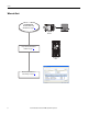
Preface How Hardware is Connected This quick start demonstrates the following possible control system. Computer Logix5000 Controller with Ethernet Connection PowerFlex 525 Drive via Embedded EtherNet/IP Adapter Esc Sel Stratix 6000™ Managed Switch 8 7 6 5 4 3 2 1 Required Software To complete examples in this quick start, you need the software described in this table. Software Required Version Required for This Task RSLogix 5000 20.00.
Preface Parts List You need these parts to complete the tasks described in this quick start. ✓ Quantity Cat. No. Description 1 25B-xyyyN1z4 PowerFlex 525 AC drive 1 1585J-M8PBJM-2 RJ45 to RJ45 Ethernet cable For a list of parts required to complete the prerequisite tasks listed in Table 1 on page 5, see the documentation describing those tasks.
Chapter 1 Prepare the PowerFlex 525 Drive Hardware In this chapter, you learn how to complete the following tasks: • Mount and wire power to a PowerFlex 525 AC drive. • Configure EtherNet/IP communication for the drive. Before You Begin You must complete these tasks before using this chapter: • The tasks described in Before Using This Publication on page 5. The example controller project used in this chapter uses a CompactLogix 5370 L3 controller.
Chapter 1 Prepare the PowerFlex 525 Drive Hardware Follow These Steps Mount the Drive on page 13 Esc Sel Esc Sel Install Power Wiring on page 13 L1/R L2/S L3/T T1/U T2/V T3/W DC- DC+ BRBR+ Configure the Embedded EtherNet/IP Adapter on page 16 12 Rockwell Automation Publication IASIMP-QS036A-EN-P - April 2013
Prepare the PowerFlex 525 Drive Hardware Chapter 1 Mount the Drive The PowerFlex 525 drive must be mounted on a flat, vertical, and level surface (or DIN rail), following the requirements for minimum clearances, ambient operating temperature, and debris protection. For complete mounting instructions, see the PowerFlex 525 Adjustable Frequency AC Drive User Manual, publication 520-UM001. Install Power Wiring Follow these steps to access the power terminals and connect the power wires.
Chapter 1 Prepare the PowerFlex 525 Drive Hardware • For frame A dives, press down and pull out on the top cover of the control module, then hold the sides and pull the control module out of the power module. Press Down on Tab and Pull Out on Cover Power Module Control Module Hold Sides of Control Module and Pull Out 2. Press and hold down the locking tab on the terminal guard, and slide the terminal guard down to remove from the power module.
Prepare the PowerFlex 525 Drive Hardware 3. Connect the AC power conductors to the drive terminals as described in the following table and tighten the screws according to the torque specifications listed in the drive user manual.
Chapter 1 Prepare the PowerFlex 525 Drive Hardware Configure the Embedded EtherNet/IP Adapter The PowerFlex 525 Embedded EtherNet/IP network adapter requires a network IP address to operate on an EtherNet/IP network. There are two methods for configuring the embedded EtherNet/IP adapter IP address: • BOOTP Server – Use BOOTP if you prefer to control the IP addresses of devices with a server. The IP address, subnet mask, and gateway addresses are provided by the BOOTP server. BOOTP is enabled by default.
Prepare the PowerFlex 525 Drive Hardware Chapter 1 6. From the Tools menu, choose Network Settings. 7. Type the Subnet Mask of the network. The Gateway address, Primary and/or Secondary DNS address, and Domain Name fields are optional. 8. Click OK. The Request History panel appears with the hardware addresses of all devices issuing BOOTP requests. 9. Select the appropriate device, that is, the device with the MAC ID that matches your PowerFlex 525 drive. 10. Click Add to Relation List.
Chapter 1 Prepare the PowerFlex 525 Drive Hardware 13. To permanently assign this configuration to the adapter, wait for the adapter to appear in the Relation List panel and select it. 14. Click Disable BOOTP/DHCP. When power is cycled, the adapter uses the assigned configuration and does not issue a BOOTP request. IMPORTANT If you do not click Disable BOOTP/DHCP, on a power cycle, the host controller clears the current IP configuration and begins sending BOOTP requests again.
Chapter 2 Add a PowerFlex 525 Drive to a Controller Project In this chapter, you add a PowerFlex 525 drive to a controller project and configure the drive. You also download the project to the controller so you can verify communication with the drive. Before You Begin You must complete these tasks before using this chapter: • The tasks described in Before Using This Publication on page 5. • Prepare the PowerFlex 525 drive as described in Chapter 1, Prepare the PowerFlex 525 Drive Hardware on page 11.
Chapter 2 Add a PowerFlex 525 Drive to a Controller Project Follow These Steps Add the Drive to the Controller Project on page 21 Download the Project and Connect to the Drive on page 25 Edit the Drive Parameters on page 26 Test the PowerFlex 525 Drive Tags on page 28 20 Rockwell Automation Publication IASIMP-QS036A-EN-P - April 2013
Add a PowerFlex 525 Drive to a Controller Project Chapter 2 Add the Drive to the Controller Project IMPORTANT The tasks described in this section use a RSLogix 5000 project for a CompactLogix 5370 L3 controller. CompactLogix 5370 L3 controllers require that you use RSLogix 5000 software, version 20.00.00 or later. The Studio 5000 Logix Designer application version 21.00 or later can also be used. The steps are very similar to the RSLogix 5000 project shown in this section.
Chapter 2 Add a PowerFlex 525 Drive to a Controller Project The Module Properties dialog box for the drive appears. 6. Type a Name for the drive. 7. Type the same IP address for the drive as the IP address you assigned to the EtherNet/IP adapter in Configure the Embedded EtherNet/IP Adapter on page 16. 8. Click Change. The Module Definition dialog box appears. 9. In the Module Definition dialog box, complete the following tasks. a.
Add a PowerFlex 525 Drive to a Controller Project Chapter 2 11. Click the Drive tab. 12. From the device toolbar, click Upload. A Connection Browser appears. 13. Navigate to and select the desired drive. 14. Click OK. If you have not previously connected to a PowerFlex 525 drive, a Creating Device Database File dialog box appears and shows the progress of the database creation. No action is necessary. IMPORTANT If your computer already has a database, the software does not create a new one.
Chapter 2 Add a PowerFlex 525 Drive to a Controller Project When the connection is complete, the Upload dialog box appears. 15. Click Upload Entire Device. An Upload dialog box appears and shows the progress of the upload. If there are any differences between the drive in your project and the drive to which you are connecting, a Module Definition Differences Found dialog box appears and shows the differences. If this is the drive you want to add to your project, click OK.
Add a PowerFlex 525 Drive to a Controller Project Chapter 2 Download the Project and Connect to the Drive 1. Click the Controller Status icon and choose Download. The Download Warning dialog box appears. 2. Click Download. The controller project goes online with the controller and the project is downloaded. Once the project has successfully downloaded to the controller, if the Module Properties window for the drive is open, a connection is made with the drive.
Chapter 2 Add a PowerFlex 525 Drive to a Controller Project Edit the Drive Parameters 1. If necessary, open the Module Properties dialog box for the drive and, on the Drive tab, click Parameters in the toolbar. The Parameter List dialog box appears. 2. To change drive parameters, click the Value column cell for the appropriate parameter and make a change. Depending on the Value cell, choose the appropriate value from pull-down menu or type your value.
Add a PowerFlex 525 Drive to a Controller Project Chapter 2 3. Change the parameters listed in the following table to values shown.
Chapter 2 Add a PowerFlex 525 Drive to a Controller Project Test the PowerFlex 525 Drive Tags 1. Put the controller in RUN mode. RUN REM PROG 2. Double-click Controller Tags. 3. On the Monitor Tags tab, expand the PowerFlex 525 drive output tag and change the ClearFaults tag to 1 to clear any initial faults. 4. Change the ClearFaults tag back to 0. 5. Expand the PowerFlex 525 drive input tag and verify that the Ready tag value is 1. This tag indicates that the drive is ready to start.
Add a PowerFlex 525 Drive to a Controller Project Chapter 2 6. In the drive output tags, change the CommandedFreq tag to 15000 engineering units (this is approximately 59.5 Hz). WARNING: If there is a motor attached to your drive, completing the next step causes the motor to turn. 7. Change the Start tag to 1. The display on the drive registers the speed increase in Hz until the value entered at the reference tag is reached. 8. Change the Start tag back to 0.
Chapter 2 Add a PowerFlex 525 Drive to a Controller Project 9. Change the Stop tag to 1. The display on the drive shows a speed decrease until the drive reaches 0.00 Hz. 10. Change the Stop tag back to 0. 11. Go Offline. By starting and stopping the drive, you verified the following conditions exist in your application: • The controller is correctly communicating with the drive. • The drive can receive and execute simple commands.
Index B BOOTP/DHCP utility 9, 16-18 C connections hardware 9 D drive parameters edit in RSLogix 5000 software 26-27 edit in Studio 5000 environment 26-27 drive preparation mount 13 wire power 13 drive tags test in RSLogix 5000 software 28-30 test in Studio 5000 environment 28-30 E environment Studio 5000 9, 21-30 Ethernet adapter assign IP address 16-18 H Q quick starts for devices in Logix5000 control systems 7 R requirements hardware preparation 11 parts 11 prerequisite tasks 5-6 software 9 RSLogix
Index 32 Rockwell Automation Publication IASIMP-QS036A-EN-P - April 2013
Rockwell Automation Support Rockwell Automation provides technical information on the Web to assist you in using its products. At http://www.rockwellautomation.com/support/, you can find technical manuals, a knowledge base of FAQs, technical and application notes, sample code and links to software service packs, and a MySupport feature that you can customize to make the best use of these tools.